Peripherals and I2C on the Cubicore Devboard
Applicable to the Cubicore Devboard (ESP32-S3 + SX1262 on RAK3112 module).
Confirm the current hardware revision, pinout allocations, and supported firmware features in the Cubicore Devboard product documentation before deploying in field production.
The Cubicore Devboard uses a 1:1 direct mapping between its physical silkscreen labels and the underlying ESP32-S3 microcontroller GPIO numbers. Throughout this guide, all references formatted as Devboard GPIO X (such as Devboard GPIO 9, Devboard GPIO 40, or Devboard GPIO 1) directly correspond to both the physical silk labels printed on the board headers and the numeric pin definitions in Arduino IDE sketches.
1. Overview of Onboard Expansion Ports
The Cubicore Devboard is engineered to interface seamlessly with industrial, environmental, and agricultural IoT sensors. The board provides dedicated plug-and-play connectors and standard 2.54 mm breadboard-compatible expansion headers:
- Grove / JST I2C Connector (
J6): A dedicated 4-pin connector routed to the primary hardware I2C bus (Devboard GPIO 9for SDA andDevboard GPIO 40for SCL). Supports plug-and-play connection with hundreds of standard Grove, Qwiic, and STEMMA QT I2C sensors. - Onboard Battery Voltage Divider (
Devboard GPIO 1): An ultra-low-power 1.0 MΩ / 1.5 MΩ resistor divider for reading real-time Li-Po battery voltage without drawing excessive idle current. - Dual 18-Pin Headers (
J1&J2): Exposes secondary I2C, hardware SPI, UART, analog inputs (ADCs), and general-purpose I/O pins.
The Devboard operates strictly on 3.3V logic levels. Do not connect 5V I2C peripherals directly to the Devboard without an inline bidirectional logic level shifter, as voltages exceeding 3.6V will permanently damage the GPIO pins.
2. Pinout & Header Reference
The physical pins on the Cubicore Devboard headers are labeled with their direct GPIO assignments:
Header J1 (Left 18-Pin Header)
| Pin # | Silkscreen Label | Devboard GPIO | Primary Function / Notes |
|---|---|---|---|
| 1 | GND | — | Ground |
| 2 | 3V3 | — | +3.3V Regulated System Power Rail |
| 3 | GPIO45 | Devboard GPIO 45 | General I/O / Onboard Blue LED |
| 4 | GPIO46 | Devboard GPIO 46 | General I/O / Onboard Green LED |
| 5 | GPIO1 | Devboard GPIO 1 | Analog In (AIN0) / Onboard Battery Voltage Divider |
| 6 | GPIO2 | Devboard GPIO 2 | General I/O |
| 7 | GPIO9 | Devboard GPIO 9 | Primary I2C SDA (Shared with Grove Connector J6) |
| 8 | GPIO4 | Devboard GPIO 4 | Internal RF Switch Power (Do Not Use) |
| 9 | GPIO10 | Devboard GPIO 10 | SPI MISO |
| 10 | GPIO11 | Devboard GPIO 11 | SPI MOSI |
| 11 | GPIO12 | Devboard GPIO 12 | SPI CS / General I/O |
| 12 | GPIO13 | Devboard GPIO 13 | SPI SCK |
| 13 | GPIO14 | Devboard GPIO 14 | Analog In (AIN1) / General I/O |
| 14 | GPIO18 | Devboard GPIO 18 | Secondary I2C SCL (Wire1) |
| 15 | GPIO17 | Devboard GPIO 17 | Secondary I2C SDA (Wire1) |
| 16 | GPIO21 | Devboard GPIO 21 | General I/O |
| 17 | BAT | — | +BATT Positive Battery Terminal |
| 18 | GND | — | Ground |
Header J2 (Right 18-Pin Header)
| Pin # | Silkscreen Label | Devboard GPIO | Primary Function / Notes |
|---|---|---|---|
| 1 | 3V3 | — | +3.3V Regulated System Power Rail |
| 2 | GND | — | Ground |
| 3 | GPIO42 | Devboard GPIO 42 | General I/O |
| 4 | GPIO41 | Devboard GPIO 41 | General I/O |
| 5 | RST | CHIP_PU | Hardware System Reset (Active Low) |
| 6 | GPIO0 | Devboard GPIO 0 | Bootloader / Flash Mode Trigger |
| 7 | GPIO40 | Devboard GPIO 40 | Primary I2C SCL (Shared with Grove Connector J6) |
| 8 | GPIO39 | Devboard GPIO 39 | General I/O |
| 9 | GPIO38 | Devboard GPIO 38 | General I/O |
| 10 | NC | GPIO 37 | Internal Flash Bus (Do Not Connect) |
| 11 | NC | GPIO 36 | Internal Flash Bus (Do Not Connect) |
| 12 | NC | GPIO 35 | Internal Flash Bus (Do Not Connect) |
| 13 | GPIO43 | Devboard GPIO 43 | Hardware UART0 TX |
| 14 | GPIO44 | Devboard GPIO 44 | Hardware UART0 RX |
| 15 | NC | GPIO 34 | Internal Flash Bus (Do Not Connect) |
| 16 | CHG | — | TP4054 Battery Charge Status Pin |
| 17 | BAT | — | +BATT Positive Battery Terminal |
| 18 | GND | — | Ground |
3. The Grove I2C Port (Connector J6)
The onboard 4-pin Grove connector (J6) provides a quick, solderless interface for external I2C sensor breakouts:
+-------------------------------------------------------------+
|                      GROVE CONNECTOR (J6)                   |
|                                                             |
|       Pin 1: SCL  -----> Devboard GPIO 40                   |
|       Pin 2: SDA  -----> Devboard GPIO 9                    |
|       Pin 3: VCC  -----> +3.3V (Regulated System Rail)     |
|       Pin 4: GND  -----> Ground (GND)                       |
+-------------------------------------------------------------+
To initialize the Grove I2C port in Arduino IDE sketches, pass the physical pin numbers to Wire.begin():
#include <Wire.h>

#define PIN_GROVE_SDA  9
#define PIN_GROVE_SCL  40

void setup() {
  // Initialize primary I2C bus at standard 400 kHz Fast-Mode
  Wire.begin(PIN_GROVE_SDA, PIN_GROVE_SCL, 400000);
}
4. Running the Universal I2C Address Scanner
Run this scanner sketch to verify that connected I2C devices are detected on the bus, identify matching sensor models, and print a consolidated list of all responsive 7-bit hardware addresses:
/*
 * Cubicore Devboard - Universal I2C Bus Scanner
 * Target: ESP32S3 Dev Module
 * Primary I2C (Grove J6): SDA = Devboard GPIO 9, SCL = Devboard GPIO 40
 */

#include <Wire.h>

#define PIN_GROVE_SDA  9
#define PIN_GROVE_SCL  40

void setup() {
  Serial.begin(115200);

  // Wait up to 3 seconds for USB Serial Monitor
  unsigned long start = millis();
  while (!Serial && (millis() - start < 3000));

  Serial.println("\n==========================================");
  Serial.println("   Cubicore Devboard - I2C Bus Scanner    ");
  Serial.println("==========================================");
  Serial.printf("SDA Pin: Devboard GPIO %d | SCL Pin: Devboard GPIO %d\n", PIN_GROVE_SDA, PIN_GROVE_SCL);

  // Initialize I2C bus on the Grove port pins
  Wire.begin(PIN_GROVE_SDA, PIN_GROVE_SCL);
}

void loop() {
  byte error, address;
  int deviceCount = 0;
  byte detectedAddresses[32]; // Buffer to track detected I2C addresses

  Serial.println("\nScanning I2C bus (0x01 to 0x7E)...");

  for (address = 1; address < 127; address++) {
    Wire.beginTransmission(address);
    error = Wire.endTransmission();

    if (error == 0) {
      Serial.printf(" [SUCCESS] Device found at address 0x%02X (dec %d)", address, address);

      // Known sensor identification helper
      switch (address) {
        case 0x3C: Serial.println(" -> SSD1306 / SH1106 OLED Display"); break;
        case 0x44: Serial.println(" -> SHT30 / SHT31 / SHT35 Temp & Humidity (Default)"); break;
        case 0x45: Serial.println(" -> SHT30 / SHT31 / SHT35 Temp & Humidity (ADDR Pin High)"); break;
        case 0x48: Serial.println(" -> ADS1115 16-Bit ADC / TMP102"); break;
        case 0x68: Serial.println(" -> MPU6050 IMU / DS3231 RTC"); break;
        case 0x76:
        case 0x77: Serial.println(" -> BME280 / BMP280 Environmental Sensor"); break;
        default:   Serial.println(); break;
      }

      // Record detected address
      if (deviceCount < 32) {
        detectedAddresses[deviceCount] = address;
      }
      deviceCount++;
    } else if (error == 4) {
      Serial.printf(" [ERROR] Unknown error at address 0x%02X\n", address);
    }
  }

  // Summary report of detected addresses
  if (deviceCount == 0) {
    Serial.println(" [WARN] No I2C devices found. Check cable connection, 3.3V power, and pull-ups.");
  } else {
    Serial.println("--------------------------------------------------");
    Serial.printf("Done. Total device(s) found: %d\n", deviceCount);
    Serial.print("Detected address(es): ");
    for (int i = 0; i < deviceCount && i < 32; i++) {
      Serial.printf("0x%02X (dec %d)", detectedAddresses[i], detectedAddresses[i]);
      if (i < deviceCount - 1) Serial.print(", ");
    }
    Serial.println("\n--------------------------------------------------");
  }

  delay(5000); // Repeat scan every 5 seconds
}
Expected Serial Monitor Output (with SHT30 connected):
==========================================
   Cubicore Devboard - I2C Bus Scanner
==========================================
SDA Pin: Devboard GPIO 9 | SCL Pin: Devboard GPIO 40

Scanning I2C bus (0x01 to 0x7E)...
 [SUCCESS] Device found at address 0x44 (dec 68) -> SHT30 / SHT31 / SHT35 Temp & Humidity (Default)
--------------------------------------------------
Done. Total device(s) found: 1
Detected address(es): 0x44 (dec 68)
--------------------------------------------------
5. Practical Example: Reading an SHT30 Sensor (0x44)
The Sensirion SHT30 is an industry-standard, high-precision digital temperature and relative humidity sensor widely used in IoT weather stations, agricultural nodes, and environmental monitors. It is available as a 4-pin Grove / Qwiic breakout that plugs directly into the Devboard's J6 port.
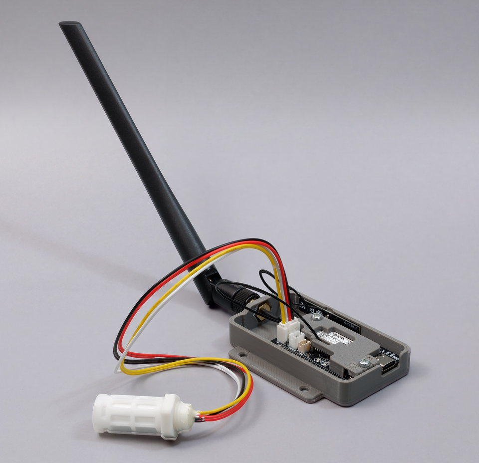
Figure: Sensirion SHT30 temperature and humidity sensor probe plugged into the onboard Grove I2C port (J6).
SHT30 Specifications:
- Default I2C Address:
0x44(7-bit address when ADDR is GND / floating;0x45when ADDR is tied HIGH to 3.3V) - Temperature Range & Accuracy: -40°C to +125°C (±0.2°C typical)
- Relative Humidity Range & Accuracy: 0% to 100% RH ($\pm 2%$ typical)
- Operating Voltage: 2.4V to 5.5V (powered safely from the Devboard's 3.3V rail)
Step 1: Install the SHT31 Library
In Arduino IDE:
- Open Tools → Manage Libraries... (or press
Ctrl+Shift+I). - Search for Adafruit SHT31.
- Install Adafruit SHT31 Library by Adafruit (this library provides full native driver support for SHT30, SHT31, and SHT35 sensors).

Figure: Installing the Adafruit SHT31 Library in the Arduino IDE Library Manager.
Step 2: SHT30 Telemetry Sketch
/*
 * Cubicore Devboard - SHT30 Temperature & Humidity Telemetry
 * Reads sensor data over Grove I2C (Devboard GPIO 9 = SDA, Devboard GPIO 40 = SCL)
 * Default I2C Address: 0x44
 */

#include <Wire.h>
#include <Adafruit_SHT31.h>

// Onboard Grove I2C pin mappings
#define PIN_GROVE_SDA  9
#define PIN_GROVE_SCL  40

Adafruit_SHT31 sht30 = Adafruit_SHT31();

void setup() {
  Serial.begin(115200);
  while (!Serial && millis() < 3000);

  Serial.println("\n==========================================");
  Serial.println("  Cubicore Devboard - SHT30 Environmental ");
  Serial.println("==========================================");

  // Initialize Wire with Grove pin mapping
  Wire.begin(PIN_GROVE_SDA, PIN_GROVE_SCL);

  // Initialize SHT30 at default hardware address 0x44
  Serial.println("[INIT] Connecting to SHT30 at address 0x44...");
  if (!sht30.begin(0x44)) {
    Serial.println("[WARN] SHT30 not found at 0x44. Checking alternate address 0x45...");
    if (!sht30.begin(0x45)) {
      Serial.println("[ERROR] SHT30 initialization failed!");
      Serial.println("        1. Check Grove 4-pin cable connection.");
      Serial.println("        2. Verify 3.3V power rail.");
      Serial.println("        3. Run I2C Scanner sketch to detect active address.");
      while (1) delay(1000);
    }
  }

  Serial.println("[SUCCESS] SHT30 sensor initialized successfully.\n");
}

void loop() {
  float temperature = sht30.readTemperature(); // Degrees Celsius (°C)
  float humidity    = sht30.readHumidity();    // Relative Humidity (% RH)

  if (!isnan(temperature) && !isnan(humidity)) {
    Serial.println("----------------------------------------");
    Serial.printf(" Temperature: %.2f °C\n", temperature);
    Serial.printf(" Humidity:    %.2f %%\n", humidity);
    Serial.println("----------------------------------------");
  } else {
    Serial.println("[WARN] Failed to read data from SHT30 sensor.");
  }

  delay(2000);
}
Expected Serial Monitor Output:

Figure: Arduino IDE Serial Monitor displaying live SHT30 telemetry readings.
==========================================
  Cubicore Devboard - SHT30 Environmental
==========================================
[INIT] Connecting to SHT30 at address 0x44...
[SUCCESS] SHT30 sensor initialized successfully.

----------------------------------------
 Temperature: 29.79 °C
 Humidity:    39.96 %
----------------------------------------
----------------------------------------
 Temperature: 29.78 °C
 Humidity:    39.81 %
----------------------------------------
6. Reading Onboard Battery Voltage (Devboard GPIO 1)
The Cubicore Devboard features an integrated, high-impedance voltage divider connected to Devboard GPIO 1 to monitor single-cell Li-Po battery levels with minimal quiescent current draw.
       V_BATT (3.7V - 4.2V)
              │
             ┌┴┐
             │ │ R1 = 1.0 MΩ (Top Resistor)
             └┬┘
              ├───> Connected to Devboard GPIO 1 (ADC1_CH0)
             ┌┴┐
             │ │ R2 = 1.5 MΩ (Bottom Resistor)
             └┬┘
              │
             GND
Voltage Divider Calculation
The divider ratio scales the raw battery voltage according to:
V_ADC = V_BATT × [R2 / (R1 + R2)] = V_BATT × [1.5 MΩ / (1.0 MΩ + 1.5 MΩ)] = V_BATT × 0.60
To calculate the true battery voltage (V_BATT) from the measured ADC voltage (V_ADC):
V_BATT = V_ADC × [(R1 + R2) / R2] = V_ADC × (2.5 / 1.5) = V_ADC × 1.6667
For a fully charged 4.2V Li-Po cell, the pin sees 4.2V × 0.60 = 2.52V, well within the ESP32-S3 ADC's linear range.
Battery Voltage Reading Sketch
/*
 * Cubicore Devboard - Battery Voltage Monitor
 * Reads onboard 1.0M / 1.5M voltage divider on Devboard GPIO 1
 */

#define PIN_VBAT_SENSE  1

// Theoretical multiplier is (1.0M + 1.5M) / 1.5M = 1.6667
// Calibrated factor accounts for resistor tolerance and ADC nonlinearity
const float VBAT_DIVIDER_RATIO = 1.6667f;

float readBatteryVoltage() {
  // Read analog voltage in millivolts using the ESP32-S3 calibrated ADC
  uint32_t adc_mv = analogReadMilliVolts(PIN_VBAT_SENSE);

  // Calculate true battery voltage
  float battery_volts = (adc_mv * VBAT_DIVIDER_RATIO) / 1000.0f;
  return battery_volts;
}

int calculateBatteryPercentage(float voltage) {
  // Standard single-cell Li-Po discharge approximation (3.27V empty to 4.20V full)
  if (voltage >= 4.20) return 100;
  if (voltage <= 3.27) return 0;
  int percentage = (int)((voltage - 3.27) / (4.20 - 3.27) * 100.0);
  return constrain(percentage, 0, 100);
}

void setup() {
  Serial.begin(115200);
  while (!Serial && millis() < 3000);

  // Configure ADC resolution (12-bit is standard for ESP32-S3)
  analogReadResolution(12);
  analogSetAttenuation(ADC_11db); // Full-scale range up to ~3.1V

  Serial.println("\n[INIT] Battery Monitor Initialized on Devboard GPIO 1.");
}

void loop() {
  float vbat = readBatteryVoltage();
  int percent = calculateBatteryPercentage(vbat);

  Serial.printf("[BATTERY] Voltage: %.2f V | State of Charge: %d %%\n", vbat, percent);
  delay(3000);
}
7. Packaging Sensor Data for LoRaWAN Payloads
In low-power LoRaWAN networks, bandwidth is limited and duty cycles are strictly enforced. You should never transmit plain text or JSON strings (e.g., {"temp":25.4}) because they create unnecessarily large packets, waste battery power, and increase RF collisions.
Instead, encode your sensor readings into a compact binary byte array:
// Example: Packing SHT30 Temperature (25.45 °C), Humidity (62.3 %), and Battery (4.12 V) into 6 Bytes
int16_t temp_encoded  = (int16_t)(temperature * 100); // 25.45 °C -> 2545 (2 Bytes)
uint16_t hum_encoded  = (uint16_t)(humidity * 100);    // 62.30 %  -> 6230 (2 Bytes)
uint16_t vbat_encoded = (uint16_t)(vbat * 1000);      // 4.120 V  -> 4120 (2 Bytes)

uint8_t payload[6];
payload[0] = (temp_encoded >> 8) & 0xFF;
payload[1] = temp_encoded & 0xFF;
payload[2] = (hum_encoded >> 8) & 0xFF;
payload[3] = hum_encoded & 0xFF;
payload[4] = (vbat_encoded >> 8) & 0xFF;
payload[5] = vbat_encoded & 0xFF;

// Payload size: Exactly 6 Bytes (Transmits in ~35 ms on LoRa SF10!)
This binary encoding demonstrates how sensor telemetry is compressed for RF transmission. The complete, end-to-end LoRaWAN implementation—including OTAA key configuration, Semtech SX1262 radio initialization, join sequences, and uplink intervals—is covered in full detail in Joining a LoRaWAN Network.
8. Troubleshooting Sensor & Bus Issues
| Symptom | Probable Cause | Recommended Fix |
|---|---|---|
I2C Scanner reports No I2C devices found | Incorrect SDA/SCL pins passed to Wire.begin() | Ensure you explicitly call Wire.begin(9, 40) to target the Grove connector (Devboard GPIO 9 = SDA, Devboard GPIO 40 = SCL). |
SHT30 initialization fails at 0x44 | Module configured with alternate address or loose cable | Check if your SHT30 breakout has its ADDR pin pulled HIGH to VCC (selects 0x45). Run the I2C scanner to verify which address is detected on the bus. |
| Sensor reads erratic values or drops communication | Missing pull-up resistors or excessive bus speed | Most Grove sensor modules contain built-in 4.7 kΩ pull-ups. For custom breakout boards, ensure pull-ups to 3V3 are present or reduce clock speed to 100 kHz (Wire.setClock(100000)). |
| Battery voltage reads 0V or floating values | ADC attenuation not configured or battery not connected | Ensure analogSetAttenuation(ADC_11db) is set. If the board is only powered by USB-C without a battery attached to BAT, the pin will read a floating or trickle-charge voltage. |
Next Steps
Now that you can capture real environmental sensor data and monitor battery levels on your Devboard, proceed to configure wireless connectivity:
- Wi-Fi and BLE — Set up the 2.4 GHz antenna, run Wi-Fi network diagnostics, sync NTP time, and use the BLE serial console.
- Joining a LoRaWAN Network — Transmit sensor telemetry over long distances to the Cubicore Gateway and The Things Network.