Joining a LoRaWAN Network with the Cubicore Devboard
Applicable to the Cubicore Devboard (ESP32-S3 + SX1262 on RAK3112 module).
Confirm the current hardware revision, pinout allocations, and supported firmware features in the Cubicore Devboard product documentation before deploying in field production.
The Cubicore Devboard uses a 1:1 direct mapping between its physical silkscreen labels and ESP32-S3 GPIO numbers. In this guide, all references formatted as Devboard GPIO X directly correspond to the physical silkscreen labels printed on the board headers and the numeric pin definitions in Arduino IDE sketches.
1. Introduction & The Gateways
Unlike Wi-Fi or Bluetooth, LoRaWAN (Long Range Wide Area Network) is designed for sending tiny amounts of data—like a temperature reading or a GPS coordinate—over distances measured in miles, not meters. Because it uses so little power, a device can run on a small battery for years.
To bridge this long-range radio signal to the internet, you need a LoRaWAN Gateway. The gateway listens for radio signals from your Devboard and forwards those messages over Wi-Fi or Ethernet to a Network Server.
For this guide, our primary examples will use our own gateways:
- Cubicore Gateway Pocket: A highly portable, compact dual-channel gateway with integrated internal antennas. Perfect for small classroom or desktop setups.
- Cubicore Gateway Hub: A desktop dual-channel gateway featuring a larger enclosure and an external high-gain blade antenna.
Note: Both of these are dual-channel gateways. They share the exact same internal architecture and require the exact same LoRaWAN configuration on your Devboard to work properly.
Prerequisites & Hardware Safety
Before writing any code or configuring the radio, ensure your hardware is properly set up:
- Cubicore Devboard mounted in its protective baseplate, connected to your workstation via a reliable USB-C data cable.
- 915 MHz LoRa Blade Antenna threaded finger-tight onto the baseplate's external RP-SMA bulkhead jack and adjusted upright. (On the factory pre-assembled Devboard, the RP-SMA bulkhead is pre-mounted to the baseplate flange and its internal MHF4 pigtail is securely held down under the Antenna Locker Plate).
- 2.4 GHz PCB Antenna connected to
ANT_WIFI(pre-installed in the baseplate channel under the locker plate). - (For Sketch 2 only) Sensirion SHT30 Sensor securely plugged into the Grove I2C port (
J6).
Never initialize or transmit with the Semtech SX1262 transceiver without attaching the 915 MHz LoRa antenna. Transmitting at high power without an antenna reflects RF energy back into the silicon power amplifiers, causing severe overheating and permanent hardware damage.
2. SX1262 Internal Pinout & Dedicated SPI Bus
The RAK3112 module integrates both the ESP32-S3 microcontroller and the Semtech SX1262 LoRa transceiver under a single metal RF shield.
They communicate internally via a dedicated SPI bus (FSPI). This means you do not need to wire any external jumper cables for LoRa operation, and the standard SPI pins on the board's header remain completely free for your own displays or SD cards.
Here is the exact internal mapping used by our firmware:
| ESP32-S3 Pin | SX1262 Pin | Function |
|---|---|---|
Devboard GPIO 7 | NSS | SPI Chip Select (Active Low) |
Devboard GPIO 47 | DIO1 | Interrupt Request (Fires when TX or RX is done) |
Devboard GPIO 8 | RESET | Hardware Reset (Active Low) |
Devboard GPIO 48 | BUSY | Transceiver Busy Status Flag |
Devboard GPIO 5 | SCK | Dedicated LoRa SPI Clock |
Devboard GPIO 3 | MISO | Master In / Slave Out |
Devboard GPIO 6 | MOSI | Master Out / Slave In |
Note: The RF Switch is driven internally by the SX1262 DIO2 pin, and the internal Temperature Compensated Crystal Oscillator (TCXO) power supply is driven by the DIO3 pin (1.8V).
3. The Things Network (TTN) & Your Secret Keys
Before writing code, your Devboard needs permission to join the network. We will use The Things Network (TTN), a global, crowdsourced LoRaWAN network server.
To join TTN securely via OTAA (Over-The-Air Activation), your Devboard requires three unique cryptographic keys. Think of this like a highly secure login system:
- DevEUI (Device Extended Unique Identifier): Think of this as the unique serial number or "username" of your specific Devboard.
- JoinEUI / AppEUI (Application EUI): Think of this as the ID of your overall project or Join Server.
- AppKey (Application Key): The super-secret master password. TTN and your Devboard use this password to encrypt your data so no one else can read it.
Step-by-Step TTN Registration
Follow these detailed steps to generate your keys and register your Devboard on TTN:
Step 3.1: Create an Application
- Go to The Things Network console and log in.
- Select your regional cluster. (If you are in the Philippines/Asia, select Asia Pacific 1 (
au1)). - Click on Applications in the top menu, then click + Create application.

Figure: Clicking the Create application button in The Things Network dashboard.
- Give your application an Application ID (e.g.,
cubicore-devboard-test) and an optional name and description.
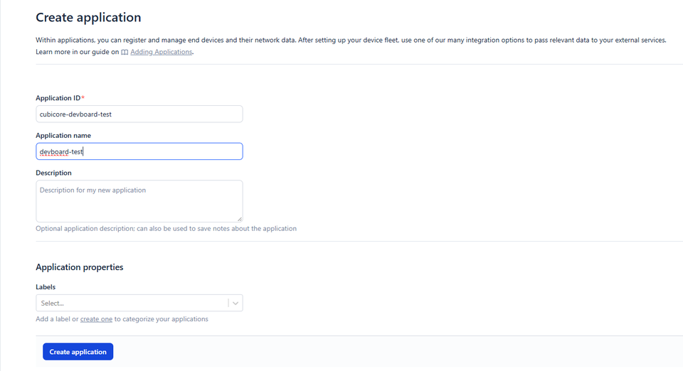
Figure: Setting the Application ID and human-readable application name.
- Click Create application.
Step 3.2: Register the End Device
Now that you have a "folder" (Application) for your project, let's add the Devboard into it.
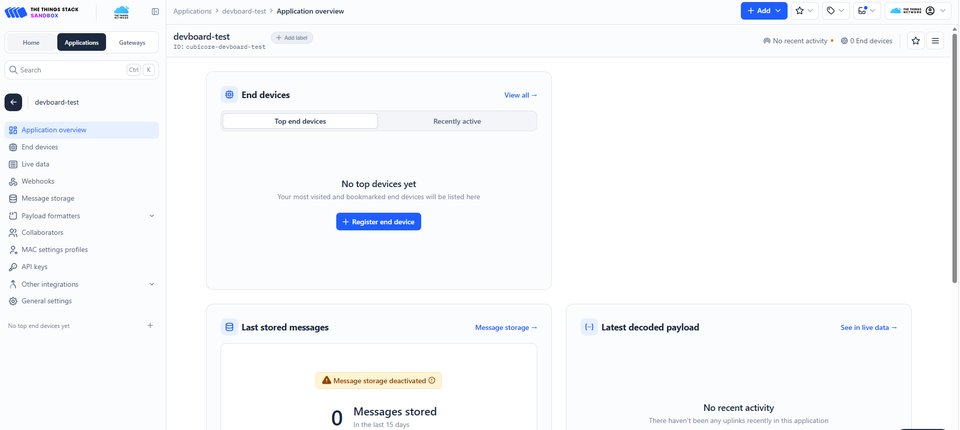
Figure: The Application overview dashboard showing the Register end device button.
- Inside your new Application, click + Register end device.
- Select Enter end device specifics manually (do not use the device repository).
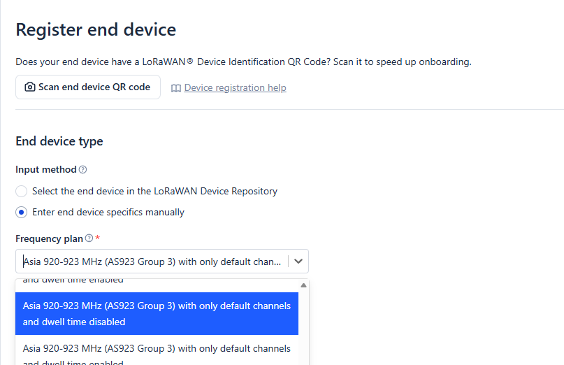
Figure: Selecting manual device entry and the AS923 Group 3 frequency plan.
- Fill out the Network Layer specifications exactly as follows (tested and confirmed stable for Philippine deployments):
- Frequency Plan:
Asia 920-923 MHz (AS923 Group 3) with only default channels and dwell time disabled - LoRaWAN Version:
LoRaWAN Specification 1.0.4 - Regional Parameters Version:
RP002 Regional Parameters 1.0.2(or1.0.4)
- Frequency Plan:
- Click Show advanced activation, LoRaWAN class and cluster settings to verify it is set to Over the air activation (OTAA).
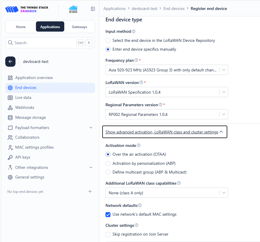
Figure: Setting LoRaWAN Specification 1.0.4, Regional Parameters, and OTAA activation mode.
Step 3.3: Enter & Generate the Secret Keys
- Scroll down to the Provisioning information section.
- JoinEUI: TTN does not generate a JoinEUI automatically; you provide it. For testing, prototyping, and educational setups, entering
0000000000000000(16 zeros) is widely standard and works reliably. (For commercial field production, an official IEEE EUI-64 or Join Server EUI is assigned). - DevEUI: Click the Generate button next to DevEUI.
- AppKey: Click the Generate button next to AppKey.
- Click the final Register end device button at the bottom of the page.
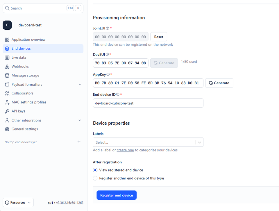
Figure: Entering JoinEUI, generating DevEUI and AppKey, and completing device registration.
Step 3.4: Copying Keys in MSB Format
Your device is now registered! On the device overview page, you will see your three keys: DevEUI, JoinEUI, and AppKey.
When you paste these into the Arduino IDE sketches below, they must be formatted in MSB (Most Significant Byte) order (also known as Big-Endian) and formatted as C-style byte arrays.

Figure: Formatting DevEUI and AppKey as MSB C-style byte arrays for the Arduino IDE.
In the TTN console, click the <> (Format as C array) button next to each key, and ensure the arrow next to it points to -> (MSB). Copy these arrays directly into the variable box provided in the sketches.
nwkKey?You might notice that RadioLib asks for both appKey and nwkKey, but TTN only gave you one AppKey.
Under LoRaWAN 1.0.4 rules, nwkKey and appKey are identical. RadioLib was built to also support newer LoRaWAN 1.1 networks (which use two separate keys). In our sketches, both appKey and nwkKey are set to the same 16-byte key provided by TTN.
4. Dual-Channel Gateway Configuration Requirements
Because the Cubicore Gateway Pocket and Cubicore Gateway Hub are affordable, dual-channel gateways, they have specific limitations compared to expensive telecom-grade gateways.
They listen on two fixed frequencies (916.6 MHz and 916.8 MHz) and only decode a specific Data Rate (DR2 or Spreading Factor 10).
If your Devboard randomly jumps to another frequency or a faster data rate (like SF7), the gateway will completely miss the message. To prevent this, our code enforces two golden rules:
- Disable Adaptive Data Rate (
node.setADR(false);): Adaptive Data Rate (ADR) is a feature where the network tells the device to transmit faster if the signal is strong. We must turn this off so the device never changes its speed. - Lock Data Rate to DR2 (
node.setDatarate(2);): This forces the Devboard to use Spreading Factor 10 (SF10) with a 125 kHz bandwidth on every single transmission.
Non-Volatile Session Persistence (Preferences.h)
Every time your board connects to TTN, it performs an "OTAA Join Request." This 5-second handshake eats up significant battery power. If your board reboots frequently, forcing it to air-join every time wastes airtime and can get your device temporarily banned by TTN (by exhausting a limited counter called DevNonce).
To solve this, our sketches use the ESP32's built-in Preferences.h library. Once the Devboard successfully joins the network, it securely saves the session keys directly into the board's internal flash memory (NVS). When you restart the Devboard, it reads these keys in milliseconds and starts sending data instantly without a new handshake!
Preferences.h is NOT an extra file, header, or second tab you have to create. It is a built-in library that comes pre-installed inside the ESP32 Arduino Board package (just like SPI.h or WiFi.h).
The sketches below are 100% single .ino files—you can copy and paste the entire block into a single blank Arduino IDE window without creating any other files or tabs.
Understanding DevNonces & Resolving "DevNonce is too small"
During testing and prototyping with the Arduino IDE, you may notice that after re-flashing your sketch or pressing the reset button, your Devboard fails to join the network.
Checking the Live data tab in the TTN Console may reveal the following error message: DevNonce is too small.

Figure: TTN Live Data stream showing the DevNonce is too small error when join nonces reset to zero.
What is a DevNonce?
In LoRaWAN Over-The-Air Activation (OTAA), a DevNonce (Device Nonce, short for "number used once") is a 2-byte counter generated by your Devboard every time it sends a Join Request.
Under the LoRaWAN 1.0.4 specification, the DevNonce must strictly increment with every join attempt. The Network Server (TTN) tracks every nonce your board has ever sent. If your board restarts and transmits a Join Request with a DevNonce that is lower than or equal to a previously used value, TTN automatically rejects the join attempt with DevNonce is too small.
Why Does This Error Occur During Prototyping?
When developing in the Arduino IDE, every time you re-upload firmware or reset the microcontroller without non-volatile storage, the node's internal state resets. If the device attempts to start its DevNonce counter from zero while TTN already recorded higher nonces from previous boots, TTN will drop the request.
The Prototyping Solution: Enabling "Resets join nonces" in TTN
For lab development and bench testing, TTN provides a setting to reset or ignore used nonces:

Figure: Enabling the Resets join nonces toggle in TTN End Device network settings.
- In the TTN Console, open your registered end device.
- Navigate to Settings → General settings → Network layer.
- Under the Advanced settings section, locate Resets join nonces and check Enabled (or click the Reset used DevNonces button).
- Click Save changes.
Why Does TTN Warn: "Resetting is insecure and makes your end device susceptible to replay attacks"?
When enabling this setting, TTN displays a warning regarding security vulnerabilities:
- What is a Replay Attack? If a malicious eavesdropper with an inexpensive radio receiver records your Devboard's wireless join packet over the air, they could re-transmit (replay) that exact recorded radio frame later to impersonate your device, hijack the session, or disrupt network traffic.
- How Incrementing Nonces Prevent Attacks: By requiring strictly incrementing, never-repeated DevNonces, TTN ensures that replayed packets are immediately detected and discarded.
- Significance for This Project: In an educational classroom or prototyping lab, enabling Resets join nonces is completely safe and avoids frustrating connection blocks while experimenting. However, for commercial field deployments, resetting nonces must remain disabled to protect data integrity.
This is also a major reason why our firmware utilizes Non-Volatile Session Persistence (Preferences.h): by caching the cryptographic session keys in onboard Flash memory, the Devboard skips the OTAA handshake entirely upon reboot, conserving DevNonces and preventing DevNonce is too small errors in the first place!
Understanding Frame Counters (FCntUp) & Silent Packet Drops on Reboot
Another essential LoRaWAN security feature is the Frame Counter (FCntUp):
- Every single uplink transmitted by your Devboard carries an incrementing sequence number (
FCntUp = 1, 2, 3...). - TTN enforces strict replay protection: it only accepts packets with an
FCntUpstrictly higher than the highest counter it has already seen.
The Reboot Trap:
If your Devboard sends Uplink 1 (FCnt = 1) and Uplink 2 (FCnt = 2), TTN records that the latest counter is 2.
If you then press the RST button on the Devboard:
- If the board reboots and restores a session where
FCntUpwas still recorded as0, its first post-reset transmission will beFCnt = 1. - The radio on the Devboard will transmit successfully (Serial Monitor will report
SUCCESS), and the gateway will forward it. - However, TTN will silently drop the packet! Because TTN already processed
FCnt = 2, it treatsFCnt = 1andFCnt = 2as illegal duplicate/replay packets. - Only when your board reaches
FCnt = 3(higher than TTN's recorded2) will TTN accept the uplink and display it in the Live Data stream!
The Solution in Code:
To prevent silent packet drops upon reboot, our sketches automatically update the session state in Flash NVS after every successful transmission:
// Save updated Frame Counter (FCntUp) to NVS so reboots don't drop packets
prefs.begin("lorawan", false);
prefs.putBytes("session", node.getBufferSession(), SESSION_BUF_SIZE);
prefs.end();
ESP32 Flash memory has a typical endurance of ~100,000 write cycles. For our classroom test sketches, writing to Flash after every transmission is completely safe. However, in production battery-powered field nodes (explored in Chapter 8: Power and Battery Optimization), we preserve FCntUp inside ultra-low-power ESP32 RTC Fast Memory during Deep Sleep—saving both Flash wear and battery power!
5. Sketch 1: Basic LoRaWAN Join & Ping
This sketch introduces the RadioLib library, performs the standard OTAA network join, and transmits an incrementing packet counter with a pseudo-random test number. It is completely self-contained in a single .ino file.
Visual LED Status Indicators
This sketch utilizes the onboard LEDs for real-time visual diagnostics:
- Blue LED (
Devboard GPIO 45): Illuminates solid while the SX1262 is actively transmitting RF. - Green LED (
Devboard GPIO 46): Pulses on successful network join and flashes twice when an uplink is acknowledged.
Library Setup: Open the Arduino IDE Library Manager (Tools → Manage Libraries...) and install RadioLib by Jan Gromes (v7.4.0 or newer).

Figure: Installing the RadioLib library by Jan Gromes in the Arduino IDE Library Manager.
/*
 * Cubicore Devboard - LoRaWAN Dual-Channel Test Node (Sketch 1)
 * Target: ESP32S3 Dev Module | Module: RAK3112 (SX1262)
 * Profile: LoRaWAN 1.0.4 OTAA on AS923-3 (Fixed 916.6 / 916.8 MHz, DR2 / SF10)
 * Note: Entire sketch runs from a SINGLE .ino file.
 */

#include <RadioLib.h>
#include <SPI.h>
#include <Preferences.h> // Built-in to ESP32 Arduino core (no extra file needed!)

// ========================================================
// ⬇️ PASTE YOUR TTN KEYS HERE (MSB / C-Array format) ⬇️
// ========================================================
uint64_t joinEUI = 0x0000000000000000;
uint64_t devEUI  = 0x70B3D57ED007940B;
uint8_t  appKey[] = { 0xB0, 0x7B, 0x60, 0xC1, 0x7E, 0xD0, 0x58, 0xFE, 0x8D, 0x3B, 0x76, 0x54, 0x10, 0x63, 0xD0, 0xB1 };
uint8_t  nwkKey[] = { 0xB0, 0x7B, 0x60, 0xC1, 0x7E, 0xD0, 0x58, 0xFE, 0x8D, 0x3B, 0x76, 0x54, 0x10, 0x63, 0xD0, 0xB1 };
// ========================================================

// Internal SX1262 SPI Pins
#define LORA_NSS     7
#define LORA_DIO1    47
#define LORA_RESET   8
#define LORA_BUSY    48
#define LORA_SCK     5
#define LORA_MISO    3
#define LORA_MOSI    6

// Onboard User LEDs
#define PIN_LED_BLUE   45  // RF TX active indicator
#define PIN_LED_GREEN  46  // Join success & uplink confirmation

// Dedicated SPI peripheral bus for SX1262
SPIClass loraSPI(FSPI);
Module* loraMod = new Module(LORA_NSS, LORA_DIO1, LORA_RESET, LORA_BUSY, loraSPI);
SX1262 radio(loraMod);

// LoRaWAN node configured for AS923-3 regional band
LoRaWANNode node(&radio, &AS923_3);

// Flash NVS Session Persistence definitions
Preferences prefs;
#define NONCES_BUF_SIZE   RADIOLIB_LORAWAN_NONCES_BUF_SIZE
#define SESSION_BUF_SIZE  RADIOLIB_LORAWAN_SESSION_BUF_SIZE

// --- Prototyping Toggle: Set to true if you reset keys/nonces on TTN! ---
const bool FORCE_FRESH_JOIN = false;

// --- Helper void in the same .ino file to manage session saving/restoring ---
void handlePreferences() {
  prefs.begin("lorawan", false);

  // If you reset nonces or regenerated keys on TTN, wipe the stale Flash session
  if (FORCE_FRESH_JOIN) {
    Serial.println(F("[NVS] FORCE_FRESH_JOIN enabled. Wiping old session from Flash..."));
    prefs.clear();
  }

  // 1. Try to restore previous session from Flash NVS
  if (prefs.isKey("nonces") && prefs.isKey("session")) {
    Serial.println(F("[NVS] Restoring saved session from Flash..."));
    uint8_t noncesBuf[NONCES_BUF_SIZE];
    uint8_t sessionBuf[SESSION_BUF_SIZE];
    prefs.getBytes("nonces", noncesBuf, NONCES_BUF_SIZE);
    prefs.getBytes("session", sessionBuf, SESSION_BUF_SIZE);
    node.setBufferNonces(noncesBuf);
    node.setBufferSession(sessionBuf);
    node.activateOTAA(); // Resumes saved session without air-join
  }

  // 2. If no saved session, or if restored session failed, send OTAA Join Request (with retries)
  if (!node.isActivated()) {
    Serial.println(F("[NETWORK] No active session. Starting OTAA Join..."));
    int attempt = 1;
    while (!node.isActivated() && attempt <= 5) {
      Serial.printf("[NETWORK] OTAA Join Attempt %d of 5... ", attempt);
      digitalWrite(PIN_LED_BLUE, HIGH);
      int16_t joinState = node.activateOTAA();
      digitalWrite(PIN_LED_BLUE, LOW);

      if (joinState == RADIOLIB_LORAWAN_NEW_SESSION) {
        Serial.println(F("SUCCESS!"));
        // Cache complete buffers to NVS
        prefs.putBytes("nonces", node.getBufferNonces(), NONCES_BUF_SIZE);
        prefs.putBytes("session", node.getBufferSession(), SESSION_BUF_SIZE);
        Serial.println(F("[NVS] New session cached to Flash successfully."));
        break;
      } else {
        Serial.printf("FAILED (Error: %d). Retrying in 5s...\n", joinState);
        delay(5000);
        attempt++;
      }
    }
  } else {
    Serial.println(F("[NVS] Session restored successfully! Ready for uplinks."));
  }
  prefs.end();

  // 3. Halt if connection failed after all attempts
  if (!node.isActivated()) {
    Serial.println(F("\n[HALT] Device not joined. Check antenna, gateway, and TTN keys."));
    while (true) {
      digitalWrite(PIN_LED_BLUE, !digitalRead(PIN_LED_BLUE));
      delay(250);
    }
  }
}

void setup() {
  Serial.begin(115200);
  while (!Serial && millis() < 3000);

  pinMode(PIN_LED_BLUE, OUTPUT);
  pinMode(PIN_LED_GREEN, OUTPUT);
  digitalWrite(PIN_LED_BLUE, LOW);
  digitalWrite(PIN_LED_GREEN, LOW);

  // Initialize dedicated SX1262 SPI bus
  loraSPI.begin(LORA_SCK, LORA_MISO, LORA_MOSI, LORA_NSS);

  Serial.print(F("[RADIO] Initializing SX1262... "));
  if (radio.begin() != RADIOLIB_ERR_NONE) {
    Serial.println(F("FAILED. Check hardware connection."));
    while (1);
  }

  // Configure TCXO (1.8V on DIO3) and internal RF switch (DIO2)
  radio.setTCXO(1.8);
  radio.setDio2AsRfSwitch(true);
  Serial.println(F("SUCCESS."));

  Serial.print(F("[LORAWAN] Initializing stack (AS923-3)... "));
  if (node.beginOTAA(joinEUI, devEUI, nwkKey, appKey) != RADIOLIB_ERR_NONE) {
    Serial.println(F("FAILED. Verify TTN Keys."));
    while (1);
  }
  Serial.println(F("SUCCESS."));

  // DUAL-CHANNEL GATEWAY CONFIGURATION RULES
  node.setADR(false);
  node.setDatarate(2);
  Serial.println(F("[CONFIG] ADR Disabled. Data Rate locked to DR2 (SF10)."));

  // Call our single-file preferences void to connect or restore
  handlePreferences();

  Serial.println(F("\n[NETWORK] Ready for uplinks!\n"));
  digitalWrite(PIN_LED_GREEN, HIGH);
  delay(1000);
  digitalWrite(PIN_LED_GREEN, LOW);
}

void loop() {
  static uint16_t packetCounter = 0;
  static unsigned long lastUplinkTime = 0;

  // Transmit an uplink every 30 seconds
  if (millis() - lastUplinkTime > 30000 || lastUplinkTime == 0) {
    lastUplinkTime = millis();
    packetCounter++;

    // Generate a pseudo-random test value
    uint16_t testValue = (uint16_t)(esp_random() % 900 + 100);

    // Pack into a 4-Byte Payload
    uint8_t payload[4];
    payload[0] = (packetCounter >> 8) & 0xFF;
    payload[1] = packetCounter & 0xFF;
    payload[2] = (testValue >> 8) & 0xFF;
    payload[3] = testValue & 0xFF;

    Serial.printf(">>> Sending Uplink #%u (Test Val: %u)... ", packetCounter, testValue);

    digitalWrite(PIN_LED_BLUE, HIGH);
    int16_t state = node.sendReceive(payload, sizeof(payload), 1);
    digitalWrite(PIN_LED_BLUE, LOW);

    // Verify transmission status
    if (state == RADIOLIB_ERR_NONE || state > 0) {
      Serial.println(F("SUCCESS."));
      digitalWrite(PIN_LED_GREEN, HIGH);
      delay(150);
      digitalWrite(PIN_LED_GREEN, LOW);

      // Save updated Frame Counter (FCntUp) to NVS so reboots don't drop packets
      prefs.begin("lorawan", false);
      prefs.putBytes("session", node.getBufferSession(), SESSION_BUF_SIZE);
      prefs.end();
    } else {
      Serial.printf("FAILED (Error: %d)\n", state);
    }
  }
}
Verifying Uplinks in TTN Console
Once the sketch is uploaded, open the Live data tab in your TTN Console (Application → Live data). You will see the incoming Join Request, Join Accept, and your periodic 4-byte test uplink messages forwarding with live signal statistics (RSSI and SNR):
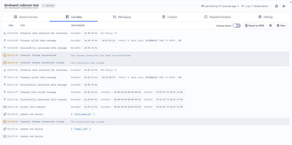
Figure: The TTN Live Data stream confirming successful OTAA activation and periodic uplinks.
6. Sketch 2: Transmitting Real Data (SHT30 Sensor)
This practical sketch integrates the Sensirion SHT30 environmental sensor via I2C (Grove port).
Payload Packing Explained: LoRaWAN is designed for incredibly small messages to save airtime and battery. Instead of sending a long, heavy text string like "Temperature: 25.42", we multiply the decimal float by 100 (2542) and send it as a compact 2-byte binary integer. This cuts down the transmission size immensely, reducing the chance of packet loss.
Library Setup: Open the Library Manager and install the Adafruit SHT31 Library (this driver covers SHT30, SHT31, and SHT35 sensors).
/*
 * Cubicore Devboard - LoRaWAN SHT30 Environmental Node (Sketch 2)
 * Sensor: Sensirion SHT30 on Grove I2C (GPIO 9 = SDA, GPIO 40 = SCL)
 */

#include <RadioLib.h>
#include <SPI.h>
#include <Wire.h>
#include <Adafruit_SHT31.h>
#include <Preferences.h> // Built-in to ESP32 Arduino core (no extra file needed!)

// ========================================================
// ⬇️ PASTE YOUR TTN KEYS HERE (MSB / C-Array format) ⬇️
// ========================================================
uint64_t joinEUI = 0x0000000000000000;
uint64_t devEUI  = 0x70B3D57ED007940B;
uint8_t  appKey[] = { 0xB0, 0x7B, 0x60, 0xC1, 0x7E, 0xD0, 0x58, 0xFE, 0x8D, 0x3B, 0x76, 0x54, 0x10, 0x63, 0xD0, 0xB1 };
uint8_t  nwkKey[] = { 0xB0, 0x7B, 0x60, 0xC1, 0x7E, 0xD0, 0x58, 0xFE, 0x8D, 0x3B, 0x76, 0x54, 0x10, 0x63, 0xD0, 0xB1 };
// ========================================================

#define LORA_NSS 7
#define LORA_DIO1 47
#define LORA_RESET 8
#define LORA_BUSY 48
#define LORA_SCK 5
#define LORA_MISO 3
#define LORA_MOSI 6

#define PIN_GROVE_SDA 9
#define PIN_GROVE_SCL 40
#define PIN_LED_BLUE 45
#define PIN_LED_GREEN 46

SPIClass loraSPI(FSPI);
Module* loraMod = new Module(LORA_NSS, LORA_DIO1, LORA_RESET, LORA_BUSY, loraSPI);
SX1262 radio(loraMod);
LoRaWANNode node(&radio, &AS923_3);

// Initialize Sensor Instance
Adafruit_SHT31 sht30 = Adafruit_SHT31();

// Flash NVS Session Persistence definitions
Preferences prefs;
#define NONCES_BUF_SIZE   RADIOLIB_LORAWAN_NONCES_BUF_SIZE
#define SESSION_BUF_SIZE  RADIOLIB_LORAWAN_SESSION_BUF_SIZE

// --- Prototyping Toggle: Set to true if you reset keys/nonces on TTN! ---
const bool FORCE_FRESH_JOIN = false;

// --- Helper void in the same .ino file to manage session saving/restoring ---
void handlePreferences() {
  prefs.begin("lorawan", false);

  // If you reset nonces or regenerated keys on TTN, wipe the stale Flash session
  if (FORCE_FRESH_JOIN) {
    Serial.println(F("[NVS] FORCE_FRESH_JOIN enabled. Wiping old session from Flash..."));
    prefs.clear();
  }

  // 1. Try to restore previous session from Flash NVS
  if (prefs.isKey("nonces") && prefs.isKey("session")) {
    Serial.println(F("[NVS] Restoring saved session from Flash..."));
    uint8_t noncesBuf[NONCES_BUF_SIZE];
    uint8_t sessionBuf[SESSION_BUF_SIZE];
    prefs.getBytes("nonces", noncesBuf, NONCES_BUF_SIZE);
    prefs.getBytes("session", sessionBuf, SESSION_BUF_SIZE);
    node.setBufferNonces(noncesBuf);
    node.setBufferSession(sessionBuf);
    node.activateOTAA(); // Resumes saved session without air-join
  }

  // 2. If no saved session, or if restored session failed, send OTAA Join Request (with retries)
  if (!node.isActivated()) {
    Serial.println(F("[NETWORK] No active session. Starting OTAA Join..."));
    int attempt = 1;
    while (!node.isActivated() && attempt <= 5) {
      Serial.printf("[NETWORK] OTAA Join Attempt %d of 5... ", attempt);
      digitalWrite(PIN_LED_BLUE, HIGH);
      int16_t joinState = node.activateOTAA();
      digitalWrite(PIN_LED_BLUE, LOW);

      if (joinState == RADIOLIB_LORAWAN_NEW_SESSION) {
        Serial.println(F("SUCCESS!"));
        // Cache complete buffers to NVS
        prefs.putBytes("nonces", node.getBufferNonces(), NONCES_BUF_SIZE);
        prefs.putBytes("session", node.getBufferSession(), SESSION_BUF_SIZE);
        Serial.println(F("[NVS] New session cached to Flash successfully."));
        break;
      } else {
        Serial.printf("FAILED (Error: %d). Retrying in 5s...\n", joinState);
        delay(5000);
        attempt++;
      }
    }
  } else {
    Serial.println(F("[NVS] Session restored successfully! Ready for uplinks."));
  }
  prefs.end();

  // 3. Halt if connection failed after all attempts
  if (!node.isActivated()) {
    Serial.println(F("\n[HALT] Device not joined. Check antenna, gateway, and TTN keys."));
    while (true) {
      digitalWrite(PIN_LED_BLUE, !digitalRead(PIN_LED_BLUE));
      delay(250);
    }
  }
}

void setup() {
  Serial.begin(115200);
  while (!Serial && millis() < 3000);

  pinMode(PIN_LED_BLUE, OUTPUT);
  pinMode(PIN_LED_GREEN, OUTPUT);
  digitalWrite(PIN_LED_BLUE, LOW);
  digitalWrite(PIN_LED_GREEN, LOW);

  // Initialize SHT30 via I2C
  Wire.begin(PIN_GROVE_SDA, PIN_GROVE_SCL);
  Serial.print(F("[SENSOR] SHT30 Check: "));

  // Try 0x44 first, then 0x45
  if (!sht30.begin(0x44) && !sht30.begin(0x45)) {
    Serial.println(F("NOT FOUND! Check wiring."));
  } else {
    Serial.println(F("FOUND"));
  }

  // Initialize Radio & LoRaWAN
  loraSPI.begin(LORA_SCK, LORA_MISO, LORA_MOSI, LORA_NSS);
  radio.begin();
  radio.setTCXO(1.8);
  radio.setDio2AsRfSwitch(true);

  node.beginOTAA(joinEUI, devEUI, nwkKey, appKey);

  // Apply 2-Channel Gateway Rules
  node.setADR(false);
  node.setDatarate(2);

  // Call our single-file preferences void to connect or restore
  handlePreferences();
}

void loop() {
  static uint16_t packetCounter = 0;
  static unsigned long lastUplinkTime = 0;

  if (millis() - lastUplinkTime > 30000 || lastUplinkTime == 0) {
    lastUplinkTime = millis();
    packetCounter++;

    // Read Data
    float t = sht30.readTemperature();
    float h = sht30.readHumidity();

    // Scale and convert to integer (NaN checks prevent bad data from crashing decoding)
    int16_t tempScaled = isnan(t) ? 0x7FFF : (int16_t)(t * 100.0f);
    uint16_t humScaled = isnan(h) ? 0xFFFF : (uint16_t)(h * 100.0f);

    // 6-Byte Payload structure
    uint8_t payload[6];
    payload[0] = (packetCounter >> 8) & 0xFF;
    payload[1] = packetCounter & 0xFF;
    payload[2] = (tempScaled >> 8) & 0xFF;
    payload[3] = tempScaled & 0xFF;
    payload[4] = (humScaled >> 8) & 0xFF;
    payload[5] = humScaled & 0xFF;

    Serial.printf("\nTemp: %.2f C | Hum: %.2f %%\n", t, h);

    // Send payload
    digitalWrite(PIN_LED_BLUE, HIGH);
    int16_t state = node.sendReceive(payload, sizeof(payload), 1);
    digitalWrite(PIN_LED_BLUE, LOW);

    if(state == RADIOLIB_ERR_NONE || state > 0) {
       Serial.println(F("SUCCESS."));
       digitalWrite(PIN_LED_GREEN, HIGH);
       delay(150);
       digitalWrite(PIN_LED_GREEN, LOW);

       // Save updated Frame Counter (FCntUp) to NVS so reboots don't drop packets
       prefs.begin("lorawan", false);
       prefs.putBytes("session", node.getBufferSession(), SESSION_BUF_SIZE);
       prefs.end();
    } else {
       Serial.printf("FAILED (Error: %d)\n", state);
    }
  }
}
7. TTN Payload Decoders
Because we used "Payload Packing" in Sketch 2 to send our data as raw binary bytes (like 0x09 0xEE), it will look like gibberish when it arrives in TTN. To view clean data on your TTN dashboard, you need to use a Payload Formatter to reverse the math and decode it back into JSON.
In the TTN Console:
-
In the Application overview, locate the End devices list and select your registered Devboard (
devboard-cubicore-test).
Figure: Selecting the registered end device from the Application overview list.
-
In the device navigation menu, select the Payload formatters tab, then click Uplink.
-
Under Formatter type, select Custom Javascript formatter.
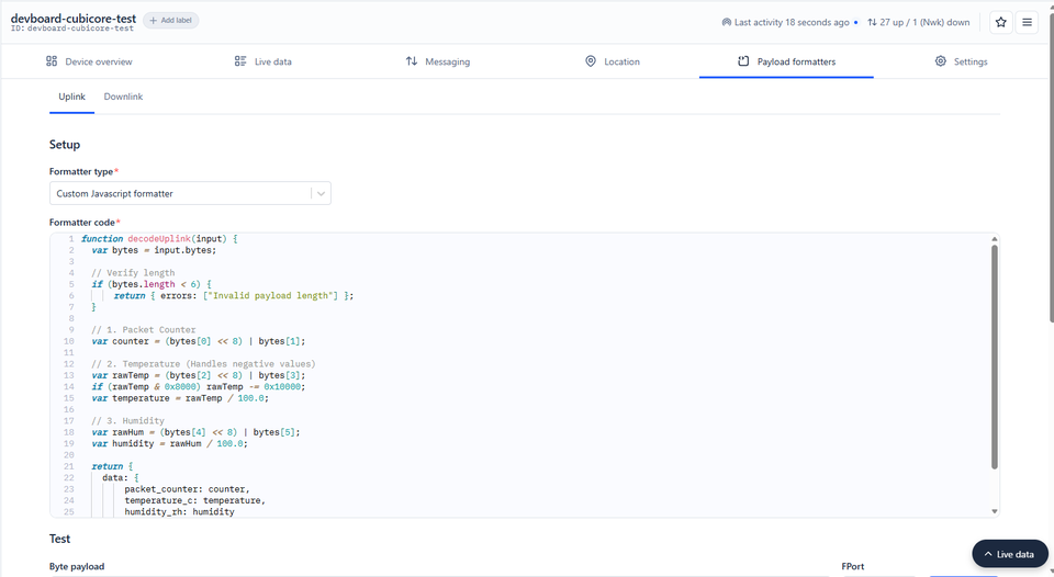
Figure: Entering the custom JavaScript uplink decoder in the Payload formatters tab.
-
Paste the decoder script below into the code editor and click Save changes.
Decoder for Sketch 2 (SHT30)
function decodeUplink(input) {
  var bytes = input.bytes;

  // Verify length
  if (bytes.length < 6) {
      return { errors: ["Invalid payload length"] };
  }

  // 1. Packet Counter
  var counter = (bytes[0] << 8) | bytes[1];

  // 2. Temperature (Handles negative values)
  var rawTemp = (bytes[2] << 8) | bytes[3];
  if (rawTemp & 0x8000) rawTemp -= 0x10000;
  var temperature = rawTemp / 100.0;

  // 3. Humidity
  var rawHum = (bytes[4] << 8) | bytes[5];
  var humidity = rawHum / 100.0;

  return {
    data: {
        packet_counter: counter,
        temperature_c: temperature,
        humidity_rh: humidity
    }
  };
}
When your next uplink arrives, open the Live data tab. TTN will automatically decode the 6-byte binary payload into human-readable JSON fields:

Figure: Decoded JSON payload displaying packet counter, temperature, and relative humidity alongside the raw radio bytes in TTN Live Data.
{
  "packet_counter": 10,
  "temperature_c": 33.02,
  "humidity_rh": 56.09
}
8. Standard 8-Channel Gateways
[!WARNING] Under Construction: Standard 8-Channel Gateway Config
This section covers multi-channel configurations for standard enterprise/commercial gateways (using SX1302/SX1303 concentrators). It is currently under active development. For all deployments utilizing the Cubicore Pocket Gateway or Cubicore Gateway Hub, follow the dual-channel guides above!
Unlike our highly affordable dual-channel gateways, massive enterprise gateways listen across 8 to 64 frequencies and decode all spreading factors simultaneously.
When you deploy onto an 8-channel enterprise network in the future, you will not have to lock your Data Rate. Instead, you can enable Adaptive Data Rate (node.setADR(true)). The network server will automatically measure your signal strength and dynamically command your Devboard to transmit faster (like SF7), massively reducing battery consumption and airtime!
9. Troubleshooting Common Errors
| Error / Code | What It Means | Root Cause & Recommended Fix |
|---|---|---|
Error: -1101RADIOLIB_ERR_NETWORK_NOT_JOINED | Device attempted to send an uplink without an active network connection. | Stale Flash Session: If you reset DevNonces or changed keys on TTN, the board is still trying to use an old cached session from Flash NVS. Set const bool FORCE_FRESH_JOIN = true; at the top of the sketch and upload once to clear Flash memory and force a brand new join. Also ensure your gateway is active and within range. |
DevNonce is too small (in TTN Console) | TTN rejected the join request because the device reused or sent a lower nonce counter. | Go to TTN Console → End device → Settings → Network layer → Advanced settings → Enable Resets join nonces. |
Serial says SUCCESS, but TTN Live Data shows nothing after reset | Frame Counter (FCntUp) out of sync. TTN silently drops uplinks with counters lower than or equal to previous transmissions. | Make sure your sketch updates the session buffer in Flash NVS after each successful transmission inside loop(), so the latest FCntUp is preserved across reboots. |
Error: -1116RADIOLIB_ERR_NO_JOIN_ACCEPT | The device sent a Join Request, but received no Join Accept downlink within the RX1/RX2 windows. | 1. Ensure the 915 MHz antenna is securely attached to ANT_LORA.2. Ensure your Cubicore Gateway Pocket or Hub is powered on and connected to the same TTN cluster ( au1).3. Verify DevEUI, JoinEUI, and AppKey match TTN. |
Error: -2RADIOLIB_ERR_CHIP_NOT_FOUND | SPI communication to the SX1262 failed. | Verify module pinout definitions. Check that LORA_NSS is GPIO 7 and FSPI is used. |
Next Steps
Now that your Devboard is successfully transmitting environmental data to the cloud, explore these advanced features:
- LoRa P2P — Direct Devboard-to-Devboard transmission without needing any gateways or network servers.
- Power and Battery Optimization — Manage the Li-Po battery charging circuit, read analog battery levels, and utilize ESP32-S3 deep sleep mode to run for years.