Getting Started with the Cubicore Devboard
Applicable to the Cubicore Devboard (ESP32-S3 + SX1262 on RAK3112 module).
Confirm the current hardware revision, pinout allocations, and supported firmware features in the Cubicore Devboard product documentation before deploying in field production.
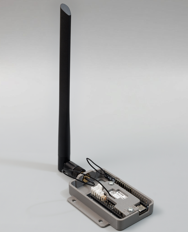
Figure: The Cubicore Devboard assembled on its protective baseplate with the antenna locker plate and 915 MHz blade antenna attached.
1. Package Contents
The Cubicore Devboard kit arrives pre-assembled from the factory with the board mounted to its protective baseplate and the antenna locker plate securely fastened in place. The package includes the following items:
| Component | Quantity | Description |
|---|---|---|
| Cubicore Devboard | 1 | Pre-assembled IoT development board with RAK3112 core module (mounted on baseplate) |
| Cubicore Devboard Baseplate & Antenna Locker Plate | 1 | Protective mounting baseplate with integrated antenna strain-relief locker plate (pre-installed) |
| MHF4 PCB Wi-Fi Antenna | 1 | 2.4 GHz adhesive omnidirectional PCB antenna for Wi-Fi and Bluetooth LE (pre-routed) |
| External 915 MHz LoRa Antenna (Blade Antenna) & RP-SMA Pigtail Cable | 1 | High-gain Sub-GHz blade antenna with chassis RP-SMA bulkhead jack (pre-installed) |
| 2.54 mm Header Strips (18-pin) | 2 | Male pin headers for breadboard and expansion port access (if not pre-soldered) |
| M3×6mm Screws | 2 | Fastener screws securing the Devboard and Antenna Locker Plate to the baseplate standoffs |
A standard USB Type-C cable capable of power and UART data transfer is required to operate and program the board, and must be supplied separately.
Many common USB-C cables (especially charging cables bundled with phones or power banks) are power-only. A power-only cable will energize the board's status LEDs, but your computer will not detect a serial COM port, preventing firmware flashing and serial monitoring. Ensure you use a verified USB-C data / sync cable.
2. Inspect the Contents

Figure: The Cubicore Devboard kit contents including the Devboard pre-assembled on its baseplate with the antenna locker plate, blade antenna, and expansion headers.
Before connecting power or assembling hardware, unbox your package and inspect all components against the checklist below:
- Cubicore Devboard (pre-mounted in baseplate with antenna locker plate secured)
- Cubicore Devboard Baseplate & Antenna Locker Plate (pre-assembled)
- MHF4 PCB Wi-Fi antenna (mounted to baseplate, connected to
BLE/WIFI) - RP-SMA chassis pigtail cable (bulkhead installed on baseplate, connected to
LORA) - External 915 MHz LoRa antenna (Blade Antenna)
- 2× 18-pin 2.54 mm male header strips (included for breadboard and expansion use)
- 2× M3 screws (fastening the Devboard and locker plate to the baseplate standoffs)
Do not connect USB, battery, or solar power without the antennas securely attached. Powering on or executing firmware that transmits via the SX1262 LoRa radio or ESP32-S3 Wi-Fi/BLE while no antenna is connected reflects RF energy directly back into the transceiver's power amplifier (PA), causing severe overheating and risking permanent silicon hardware damage. Always attach both antennas before applying power.
3. Identify the Antenna Connectors
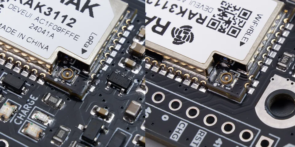
Figure: Macro view of the LoRa (left) and WiFi/BLE (right) MHF4 micro-coaxial connectors on the RAK3112 module.
The Cubicore Devboard features two micro-miniature MHF4 (IPEX4) RF receptacles located on the top surface of the RAK3112 module.
Because the module integrates both a 2.4 GHz Wi-Fi / BLE transceiver (ESP32-S3) and a Sub-GHz LoRa transceiver (SX1262), connecting the wrong antenna can severely degrade RF range or damage the transceiver output stage.
Connector Identification Guide
| Connector Label | Frequency Band | Function | Connected Antenna |
|---|---|---|---|
BLE/WIFI | 2.4 GHz (2400–2483.5 MHz) | Wi-Fi 802.11 b/g/n & Bluetooth 5.0 (LE) | MHF4 PCB Wi-Fi antenna |
LORA | 915 MHz / Sub-GHz (868–923 MHz) | LoRaWAN & P2P LoRa Transceiver | RP-SMA Pigtail + 915 MHz Blade Antenna |
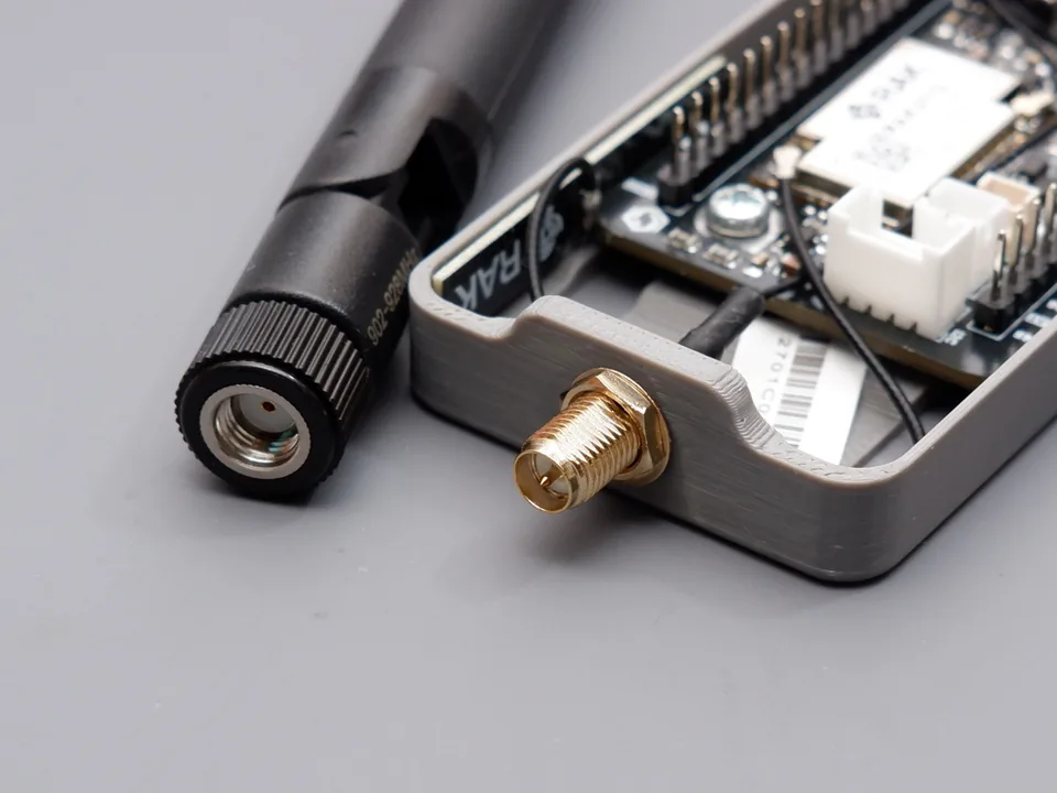
Figure: Close-up of the RP-SMA bulkhead connector mounted on the Devboard baseplate.
Understanding MHF4 vs. RP-SMA
- MHF4 (IPEX4): The ultra-compact micro-coaxial connector soldered directly on the module PCB. It has an outer diameter of ~1.5 mm and requires delicate straight-down alignment.
- RP-SMA: The standard threaded bulkhead connector mounted on the Devboard baseplate. The intermediate MHF4-to-RP-SMA pigtail cable bridges the board's
LORAport to the external blade antenna.
- Never power on or transmit without antennas connected: Transmitting without an RF load reflects power back into the SX1262 and ESP32-S3 amplifiers, risking permanent hardware burnout.
- Never swap the Wi-Fi and LoRa antennas: Transmitting at 915 MHz through a 2.4 GHz antenna causes high impedance mismatch (VSWR), degrading wireless range and stressing the RF front-end.
4. Connect the Antennas & Baseplate Assembly
The Cubicore Devboard kit arrives factory pre-assembled with the board mounted to its baseplate, the antenna locker plate secured, the internal Wi-Fi PCB antenna routed, and the LoRa pigtail connected. Under standard conditions, you only need to screw the external 915 MHz blade antenna onto the RP-SMA connector.
The detailed antenna connection and locker plate procedures below are provided on an in-case basis—for example, if you need to remove the board from the baseplate to solder the 18-pin expansion headers, inspect the circuitry, or service the antenna connections.
MHF4 micro-coaxial connectors are precision components. Follow these steps carefully to ensure reliable RF connectivity without bending the delicate center pin.
Step-by-Step MHF4 Mating Procedure
- Orientation: Position the antenna cable so the connector head sits parallel to the board surface.
- Alignment: Center the female plug directly above the male receptacle on the module (
BLE/WIFIorLORA). - Press Straight Down: Gently press straight down with your fingertip or a flat plastic tool until you feel and hear a tactile "click".
- Avoid Angle Force: Never apply pressure at an angle or slide the connector sideways across the receptacle.
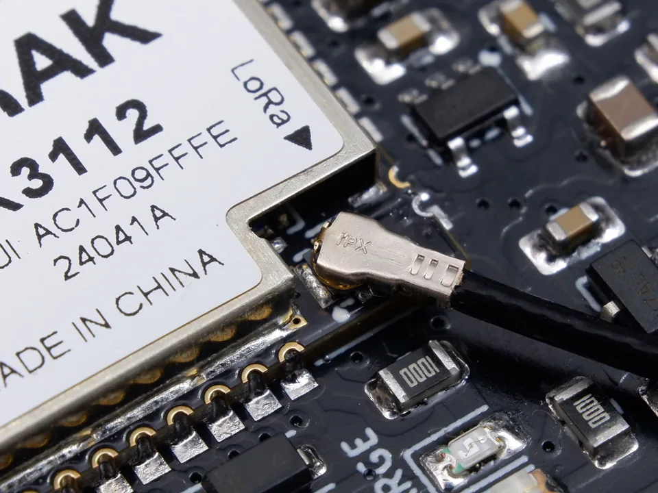
Figure: Correctly mated MHF4 connector pressed straight down and fully seated on the receptacle.
Safe Disconnection Technique
If you ever need to disconnect an MHF4 plug:
- Gently pry upward from underneath the metal collar using plastic tweezers, a spudger, or an MHF4 removal tool.
- Never pull on the thin coaxial wire itself.
Reinstalling the Board & Antenna Locker Plate (In-Case Procedure)
If you have removed the Cubicore Devboard from its baseplate (for example, to solder the expansion headers), follow these steps to reinstall the board, route the antenna cables, and secure the antenna locker plate:
Step 1: Component Overview & Baseplate Preparation
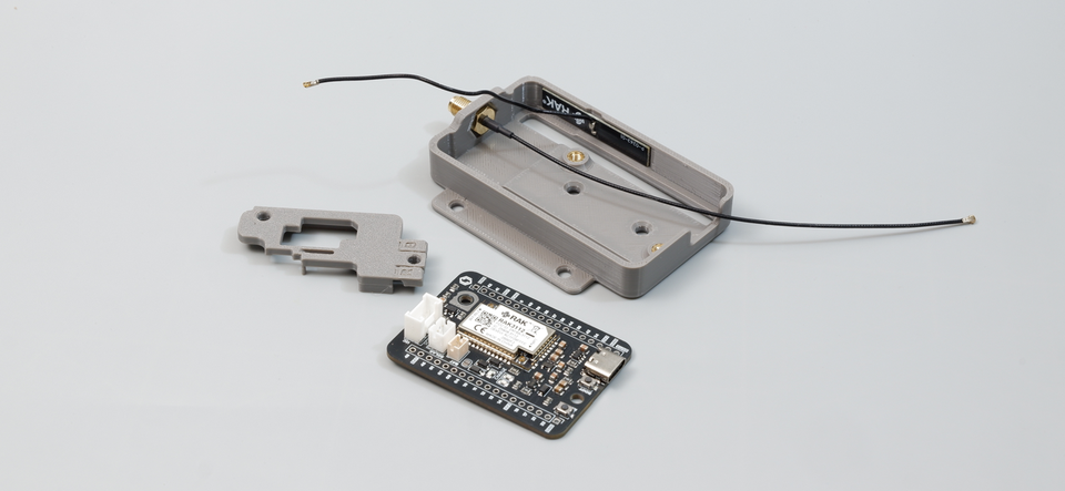
Figure: The kit components before installation: baseplate with pre-installed RP-SMA bulkhead and Wi-Fi PCB antenna, Devboard PCB, and Antenna Locker Plate.
- Position the baseplate on a clean, static-safe surface. Note the pre-installed RP-SMA bulkhead jack along the rear flange and the internal 2.4 GHz Wi-Fi PCB antenna mounted inside the baseplate channel.
- Rest the Cubicore Devboard onto the baseplate standoffs, aligning the two mounting holes with the threaded brass inserts.
Step 2: Route LoRa Pigtail Cable & Snap MHF4 Connector
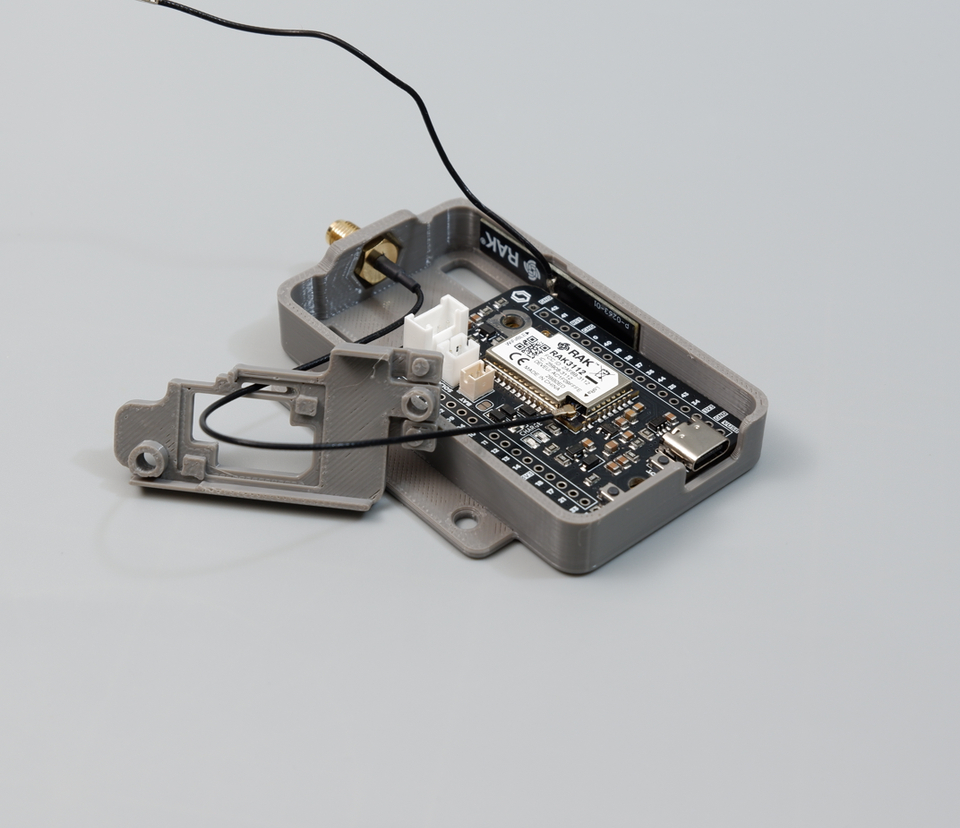
Figure: Routing the LoRa RP-SMA pigtail cable through the baseplate side channel and snapping the MHF4 connector firmly onto the module LORA port.
- Guide the thin coaxial pigtail coming from the RP-SMA bulkhead jack through the side cable channel.
- Align the MHF4 plug squarely over the male
LORAreceptacle on the RAK3112 module. - Press straight down until you feel a firm tactile click.
Step 3: Connect the Wi-Fi PCB Antenna
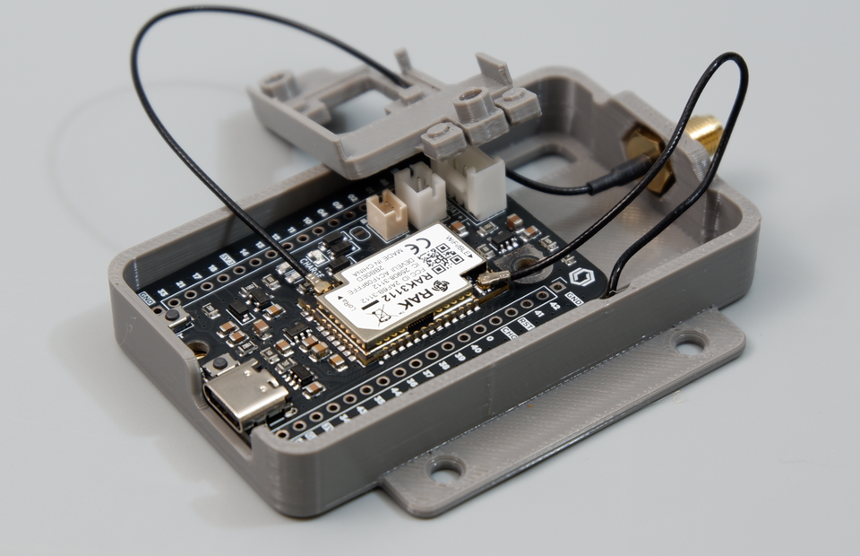
Figure: Snapping the Wi-Fi PCB antenna MHF4 connector onto the BLE/WIFI socket on the RAK3112 module.
- Route the Wi-Fi antenna coaxial lead from the baseplate channel toward the module.
- Position the connector squarely over the
BLE/WIFIreceptacle and press straight down until it clicks securely into place.
Step 4: Seat the Antenna Locker Plate & Verify Cable Clearance
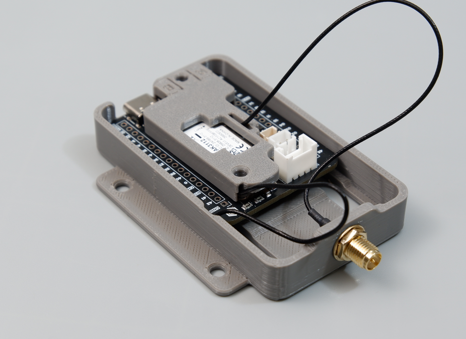
Figure: Seating the Antenna Locker Plate flush over the RAK3112 module, ensuring the Wi-Fi cable passes freely through the rear slit.
- Place the Antenna Locker Plate directly over the RAK3112 module.
- Ensure the Wi-Fi coaxial wire exits freely through the dedicated rear slit of the locker plate.
- The antenna locker plate serves as a mechanical clamp that holds both MHF4 connectors firmly in place and prevents them from popping off under vibration or cable strain.
Before screwing down the plate, inspect both antenna cables closely. The locker plate must sit completely flat and flush against the module and PCB surface. Ensure that neither the Wi-Fi nor the LoRa coaxial cable is pinched or squished under the edges of the plate, which could crush the cable dielectric or cause an RF short.
Step 5: Fasten the M3 Screws
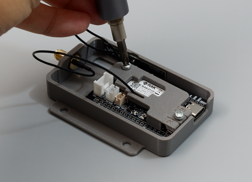
Figure: Fastening the two M3 screws through the antenna locker plate and Devboard PCB into the baseplate standoffs.
- Insert the two M3×6mm screws through the holes on the antenna locker plate, passing through the Devboard PCB into the threaded baseplate standoffs.
- Tighten both screws finger-snug using a precision screwdriver. Do not overtighten to avoid stripping the standoffs or cracking the plate.
Step 6: Verify the Completed Assembly & Attach Blade Antenna
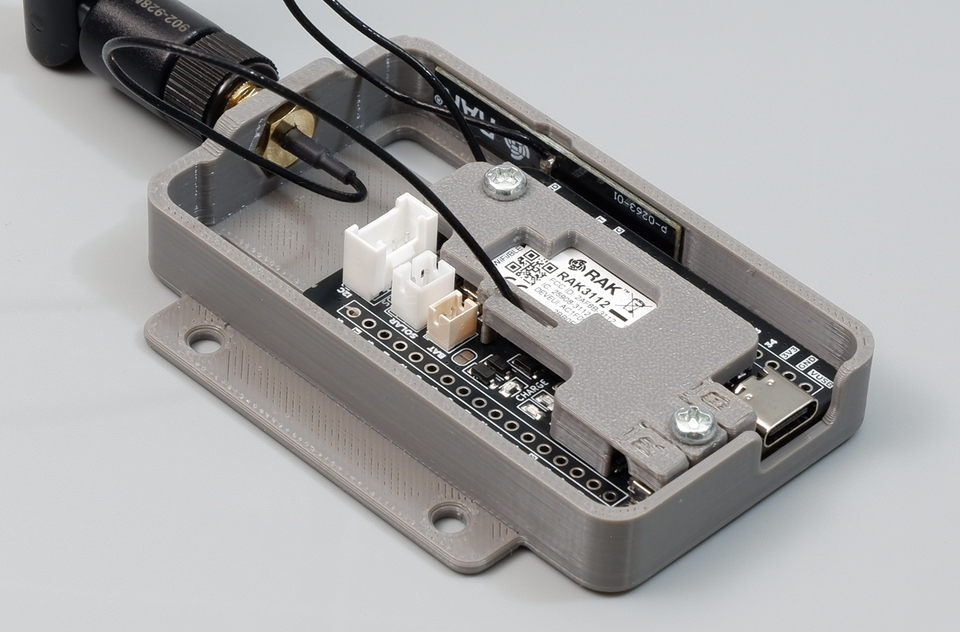
Figure: Macro view of the secured Devboard showing unobstructed access to expansion headers, USB-C, Grove, Solar, and Battery ports.
- Visually verify that both antenna connectors are firmly held beneath the locker plate.
- Check that all peripheral interfaces remain completely accessible:
- Grove I2C Port (top-right)
- Solar & Battery JST Ports (top-left)
- USB-C Port, and flexible RST ('R') and BOOT ('B') button covers (bottom-left)
- Dual 18-pin Expansion Headers (top and bottom edges)
- Screw the external 915 MHz blade antenna onto the external RP-SMA jack finger-tight. Adjust the antenna hinge to an upright vertical orientation.
5. Solder the Headers
The Cubicore Devboard includes two 18-pin 2.54 mm expansion header rows (J1 and J2) providing access to GPIOs, analog inputs, power rails, and hardware buses.
Pre-Soldering Guidelines
- Optional vs. Required: If you only use USB-C and the onboard Grove I2C connector, soldering the 18-pin headers is optional. If you intend to use a breadboard, jumper wires, or custom daughterboards, install the headers now.
- Orientation: Insert the short pin side through the top of the PCB so the long pins extend straight out through the bottom.
Recommended Breadboard Jig Technique
- Insert the two 18-pin male header strips into a solderless breadboard at the exact spacing of the Devboard rows.
- Place the Cubicore Devboard PCB over the header pins so it rests flat against the plastic insulators.
- Solder the four corner pins first, verify that the board sits completely parallel to the breadboard, and then solder the remaining pins.
- Inspect: Check each solder joint under good lighting. Ensure all joints are shiny, concave cones with no cold solder joints, dry pads, or solder bridges between adjacent pins.
All soldering work must be completed and thoroughly cleaned with isopropyl alcohol (IPA) before plugging in USB power, batteries, or external sensors.
6. Get to Know the Board
Familiarize yourself with the primary functional blocks, buttons, and indicators across the Devboard:
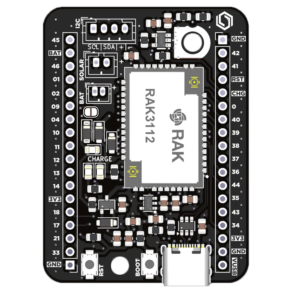
Figure: Top-down hardware overview and component layout of the Cubicore Devboard V1.3.
Key Hardware Blocks
- RAK3112 System Module: Core processing unit containing the dual-core ESP32-S3 (240 MHz, Wi-Fi, BLE) and SX1262 LoRa transceiver.
- USB Type-C Interface: System power input (5V VBUS), native USB CDC, and UART communication path for AT commands, flashing, and serial monitoring.
- Status LEDs:
- Blue LED (
GPIO45): User-programmable status indicator. - Green LED (
GPIO46): User-programmable status indicator. - Charge LED (Red): TP4054 battery charging status indicator.
- Blue LED (
- Pushbuttons:
RST(Reset): Hardware reset for the ESP32-S3.BOOT: GPIO0 bootloader mode control.
- Expansion Headers (J1 & J2): Two 18-pin headers breaking out 3.3V, 5V, GND, analog channels, SPI, UART, and general-purpose I/O.
- I2C Connector (J6): 4-pin Grove/JST sensor port wired to
I2C1(SDA = GPIO9,SCL = GPIO40). - Solar Input: 2-pin JST_PH connector for external 5V photovoltaic panels.
- Battery Input: 2-pin JST_ZH connector for 3.7V nominal Li-Po / Li-Ion batteries.
(For complete pin tables and hardware electrical parameters, refer to the full Cubicore Devboard Specification.)
7. External Connectors and Power
The Cubicore Devboard features an onboard power-path management architecture that seamlessly arbitrates between USB power, solar input, and battery storage.
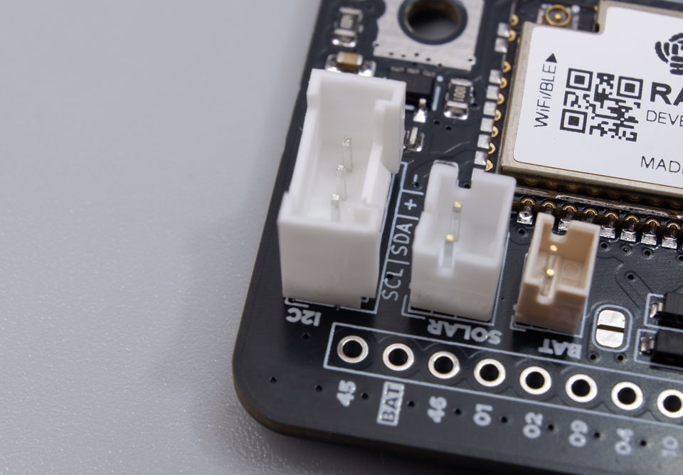
Figure: Close-up of the I2C (Grove), SOLAR, and BAT JST connectors with silkscreen polarity markings.
1. I2C Grove Connector (J6)
- Purpose: Fast, plug-and-play sensor integration without breadboard wiring.
- Compatibility: 100% compatible with standard Grove 4-pin sensors and I2C peripherals.
- Pinout:
Pin 1: SCL (GPIO40)|Pin 2: SDA (GPIO9)|Pin 3: +3.3V|Pin 4: GND. - Voltage: Regulated +3.3V supply rail.
2. Solar Panel Input (JST_PH)
- Connector Type: 2-pin JST_PH (2.0 mm pitch).
- Intended Source: 5V nominal solar panels (5.0V – 5.5V recommended open-circuit voltage).
- Polarity: Look for the silkscreen
+icon adjacent to the connector. Pin 1 is+SOL_IN, Pin 2 isGND. - Power Path: Power OR-ing diodes protect the circuit and prevent battery or USB current from back-feeding into the solar panel.
Do not connect solar panels exceeding 5.5V DC maximum. Connecting unverified 12V or 18V industrial solar panels will destroy the onboard LDO regulator and charging circuit.
3. Battery Input (JST_ZH) & TP4054 Charger
- Connector Type: 2-pin JST_ZH (1.5 mm pitch).
- Battery Chemistry: Single-cell Lithium-Polymer (Li-Po) or Lithium-Ion (Li-Ion) — 3.7V nominal, 4.2V maximum charge cutoff.
- Charging Current: Factory-set to 500 mA via onboard resistor R2. Recommended battery capacities: 500 mAh to 2000 mAh.
- Charge LED Status:
- Solid Red: Battery actively charging.
- Off: Battery fully charged (reached 4.2V cutoff) or reverse voltage.
- Twinkling / Flickering: No battery connected while on USB/Solar power.
- Always verify battery lead polarity with a multimeter before plugging in. The pin marked
+on the silkscreen must connect to the red battery lead. - Never connect multi-cell packs (7.4V / 2S), non-rechargeable batteries, or LiFePO4 cells without external regulation.
8. Reset and Boot Controls
The onboard tactile pushbuttons give you complete hardware control over MCU startup and flashing modes.
In the standard baseplate assembly, the Antenna Locker Plate extends over both pushbuttons with an integrated, 3D-printed button cover. This protective cover features embossed lettering—R for Reset and B for Boot. The compliant 3D-printed tabs flex slightly when pressed to actuate the underlying tactile switches with a crisp click, protecting the surface-mount buttons from physical impact while keeping them easily operable by finger.
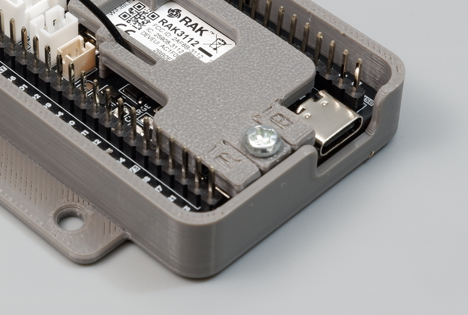
Figure: The antenna locker plate features integrated 3D-printed flexible button covers embossed with "R" (Reset) and "B" (Boot) for easy finger actuation and switch protection.
If the antenna locker plate is removed, the bare surface-mount tactile switches on the PCB are directly exposed:
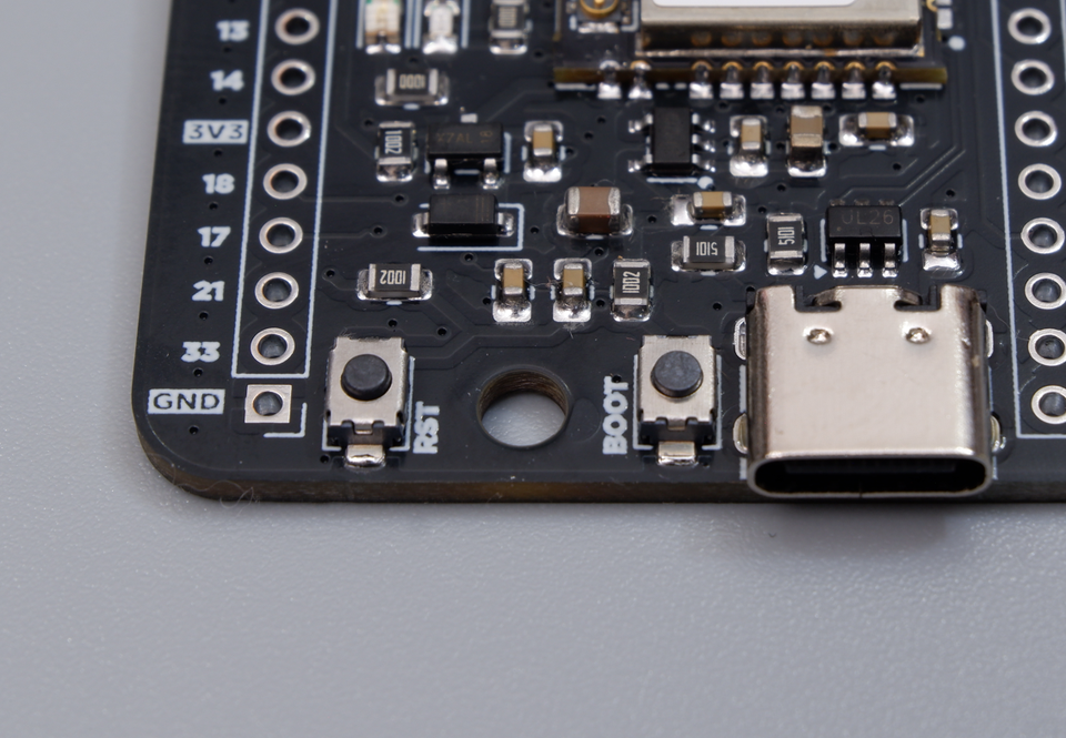
Figure: Close-up of the USB Type-C connector, BOOT button, and RST button on the bare Devboard PCB.
Button Functions
RST(Reset): Pulls the ESP32-S3CHIP_PUpin low. Pressing it restarts the CPU and executes firmware from the beginning.BOOT(GPIO0): Samples during startup to determine if the MCU should boot from internal flash or enter download mode.
Entering ROM Flash / Download Mode
When uploading new firmware or recovering from corrupted application code:
- Press and hold the
BOOTbutton. - Press and release the
RSTbutton (while continuing to holdBOOT). - Release the
BOOTbutton. - The ESP32-S3 will enter ROM bootloader mode, awaiting UART programming via USB-C.
(For full toolchain setup, driver installation, and flashing steps with the Arduino IDE, proceed to Flashing Firmware with Arduino IDE.)
9. First Inspection Checklist
Before plugging in your USB-C cable for your first power-up, run through this final readiness verification:
- Correct antenna connected to
BLE/WIFI(MHF4 PCB Wi-Fi antenna) - Correct antenna connected to
LORA(RP-SMA pigtail + external 915 MHz blade antenna) - Both MHF4 connectors snapped firmly straight down with a click
- Devboard and Antenna Locker Plate secured to the baseplate using the 2× M3×6mm screws
- Antennas positioned so exposed elements do not touch board circuitry
- Expansion header pins clean with zero solder bridges between pins
- Battery polarity verified (+ to +) if connecting an external Li-Po
- Verified USB-C cable supports data transfer (not a charge-only cable)
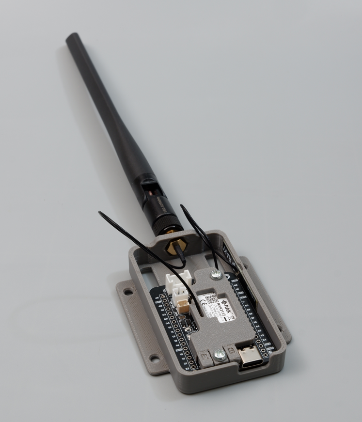
Figure: Fully assembled Devboard mounted in its baseplate with the antenna locker plate and blade antenna ready for initial power-up.
Once all checks pass, plug in your USB-C cable. The board's power rail will energize, and you are ready to begin writing firmware!
Next Steps
- Flashing Firmware (Arduino IDE) — Set up the Arduino IDE, install drivers, and upload your first firmware.
- Peripherals and I2C — Connect digital sensors and read environmental data over I2C.
- Wi-Fi and BLE — Initialize networking and test wireless communication.