Flashing Firmware (Arduino IDE)
This guide walks you through preparing the Arduino IDE toolchain, connecting the Cubicore Devboard over USB-C, configuring the correct board settings, and flashing your first diagnostic sketch. By the end, you will have a verified build environment and a blinking LED sketch running on the board.
1. Prerequisites & Hardware Setup
Before uploading firmware using the Arduino IDE, ensure you have the required hardware, cables, and software ready.
Hardware Requirements
- Cubicore Devboard (V1.3 with RAK3112 module: ESP32-S3 + SX1262).
- USB Type-C Data Cable (must support both power delivery and high-speed USB data transfer).
- Antennas Attached (2.4 GHz flexible PCB antenna on
ANT_WIFIand 915 MHz blade antenna onANT_LORA).
Never flash or execute firmware that initializes the Semtech SX1262 LoRa transceiver, Wi-Fi, or Bluetooth without securely attaching both the 915 MHz antenna and 2.4 GHz PCB antenna. Transmitting without an RF load reflects power back into the power amplifiers and can permanently damage the silicon.
Software Requirements
- Arduino IDE 2.x (version 2.2.0 or newer recommended from arduino.cc).
2. Install the ESP32 Board Package in Arduino IDE
The Cubicore Devboard is powered by the ESP32-S3 microcontroller. You must install the official Espressif ESP32 board support package in the Arduino IDE.
Step 1: Add the Board Manager URL
- Open Arduino IDE.
- Go to File → Preferences (on macOS: Arduino IDE → Settings).
- Locate the Additional boards manager URLs field.
- Paste the official Espressif package URL:
(If you already have other URLs listed, separate them with a comma).https://raw.githubusercontent.com/espressif/arduino-esp32/gh-pages/package_esp32_index.json
- Click OK to save preferences.
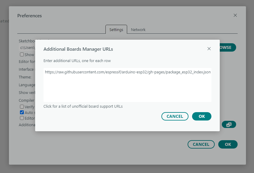
Figure: Pasting the Espressif ESP32 package URL into the Additional Boards Manager URLs field.
Step 2: Install the Board Package
- Open the Boards Manager from the left-hand sidebar (or navigate to Tools → Board → Boards Manager...).
- Type
esp32in the search box. - Locate esp32 by Espressif Systems and click Install.
- Wait for the installation to complete.
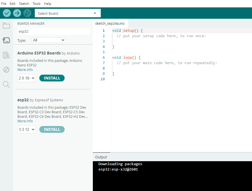
Figure: Installing the esp32 board package by Espressif Systems from the Boards Manager.
3. Connect the Board & Detect Serial Port
The Cubicore Devboard utilizes the native USB interface of the ESP32-S3 (USB CDC / JTAG with VID 0x303A and PID 0x1001), routing power and high-speed UART communication directly through the single USB-C port.
- Connect the Devboard to your computer using your USB-C data cable.
- The board will power on via the onboard RT9080-33GJ5 low-dropout regulator, supplying clean
+3.3Vto the RAK3112 module. - Confirm the board is enumerated by your operating system. On Windows, open Device Manager and look under Ports (COM & LPT) for a USB Serial Device (COMx) entry — this is the Devboard.
- Open Arduino IDE and check the port drop-down menu:
- Windows: Select the detected
COMxport (e.g.,COM5orCOM7). In Device Manager, it appears asUSB Serial Device (COMx)orESP32-S3. - macOS: Select
/dev/cu.usbmodem...or/dev/cu.usbserial-.... - Linux: Select
/dev/ttyACM0or/dev/ttyUSB0. (Ensure your user belongs to thedialoutgroup:sudo usermod -a -G dialout $USER).
- Windows: Select the detected
- In the Select Other Board and Port dialog, select ESP32S3 Dev Module under Boards and your detected COMx Serial Port (USB) under Ports, then click OK.

Figure: The Cubicore Devboard appears as a USB Serial Device under Ports (COM & LPT) in Windows Device Manager.

Figure: Selecting the ESP32S3 Dev Module board and the detected USB serial port.
You must select ESP32S3 Dev Module as the board target. This is the required board definition for the Cubicore Devboard.
4. Configure Board Settings in Arduino IDE
To ensure the compiler and bootloader match the Cubicore Devboard's 16 MB Flash and 8 MB Octal PSRAM hardware architecture, configure the Tools menu settings exactly as listed below. The entries are listed in the same order they appear in the Arduino IDE Tools menu.
| Parameter | Required Selection | Technical Rationale |
|---|---|---|
| Board | ESP32S3 Dev Module | Target architecture for ESP32-S3 dual-core LX7 |
| Port | Select your detected COM / Serial port | Communication port for flashing and serial monitoring |
| USB CDC On Boot | Enabled | Mandatory: Routes Serial.print() to the native USB-C port |
| CPU Frequency | 240MHz (WiFi) | Maximum clock frequency for optimal multi-protocol performance |
| Core Debug Level | None | Suppresses verbose system debug logs during boot |
| USB DFU On Boot | Disabled | Not required; USB CDC handles serial and upload traffic |
| Erase All Flash Before Sketch Upload | Disabled | Preserves the filesystem and NVS contents between uploads |
| Events Run On | Core 1 | Runs the Arduino events task on the second LX7 core |
| Flash Mode | QIO 80MHz | High-speed 4-bit Quad SPI flash execution |
| Flash Size | 16MB (128Mb) | Matches the 16 MB Quad SPI (QIO) Flash on the RAK3112 |
| JTAG Adapter | Disabled | Onboard USB-JTAG debugging not used for standard uploads |
| Arduino Runs On | Core 1 | Runs the main setup() / loop() sketch on the second LX7 core |
| USB Firmware MSC On Boot | Disabled | Prevents the board from mounting as a mass-storage device |
| Partition Scheme | 16M Flash (3MB APP/9.9MB FATFS) | Allocates ample application space and internal filesystem |
| PSRAM | OPI PSRAM | Enables the 8 MB Octal SPI (OPI) PSRAM memory bus |
| Upload Mode | UART0 / Hardware CDC | Selects the native USB-C (Hardware CDC) upload path |
| Upload Speed | 921600 | High-speed firmware uploading (fallback to 115200 if cable is long) |
| USB Mode | Hardware CDC and JTAG | Exposes the ESP32-S3 native USB CDC and JTAG interface |
| Zigbee Mode | Disabled | Zigbee stack not required for Wi-Fi / BLE / LoRa operation |
Because the Devboard uses native ESP32-S3 USB CDC rather than an external CP2102/CH340 chip, USB CDC On Boot must be set to Enabled. If disabled, Serial.begin(115200) will not output messages to the Arduino Serial Monitor.
The screenshot below shows the required Tools menu configuration on the Cubicore Devboard:
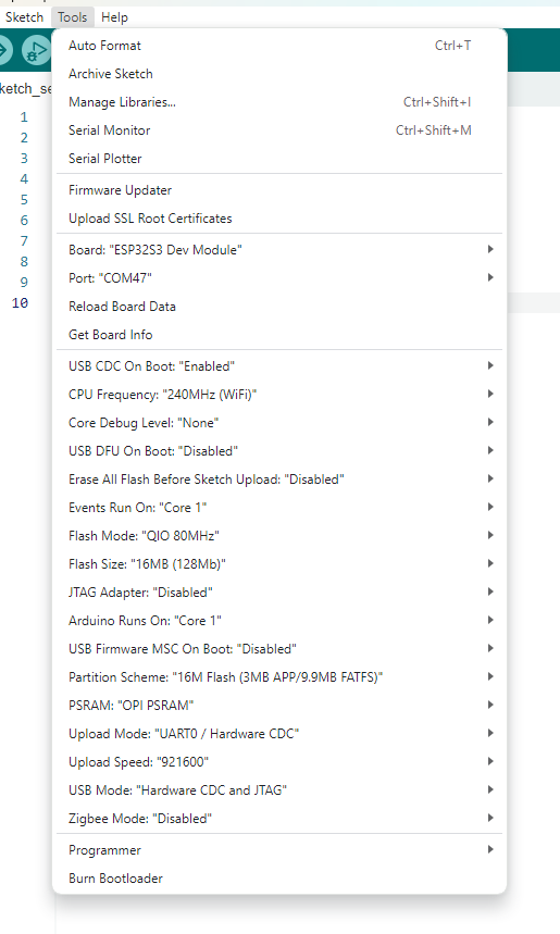
Figure: The Arduino IDE Tools menu with all settings configured for the Cubicore Devboard (ESP32S3 Dev Module, 16 MB Flash, OPI PSRAM).
5. Manual Bootloader Mode (BOOT & RST Sequence)
Modern versions of the ESP32 Arduino Core trigger automatic reset and download mode via USB DTR/RTS signals. However, if an upload times out or displays A fatal error occurred: Failed to connect to ESP32-S3, you can place the board into ROM Bootloader Mode manually:
Locating the Controls
- On the Pre-Assembled Baseplate (Default): The Antenna Locker Plate extends over both pushbuttons with an integrated, compliant 3D-printed cover featuring embossed lettering—
Bfor Boot andRfor Reset. You can actuate the underlying tactile switches directly by pressing the flexibleBandRtabs with your finger. - On the Bare PCB: If the locker plate has been removed, the physical surface-mount tactile switches labeled
BOOTandRSTare located adjacent to the USB-C port.
| Physical Control | Locker Plate Cover | Board Label | ESP32-S3 Pin | Function |
|---|---|---|---|---|
| BOOT Button | Embossed B | BOOT / IO0 | GPIO 0 | Pulls GPIO0 low to force ROM Download Mode on reset |
| RST Button | Embossed R | RST | CHIP_PU | Hardware system reset line (active low) |
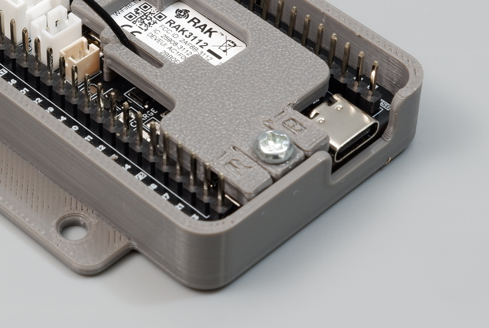
Figure: The antenna locker plate features integrated 3D-printed flexible button covers embossed with "R" (Reset) and "B" (Boot) for easy finger actuation.
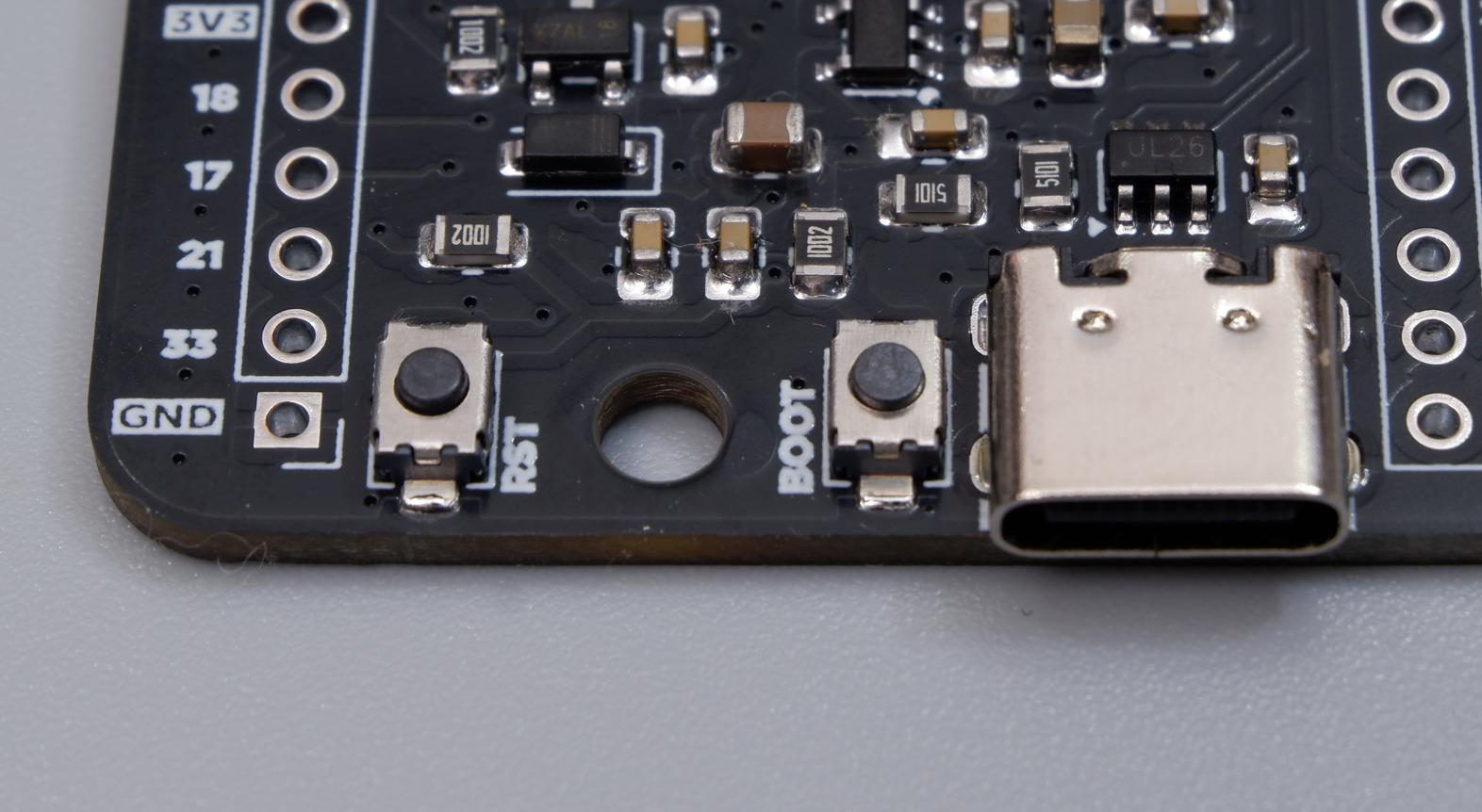
Figure: Close-up of the USB Type-C connector, BOOT button, RST button, and M3 mounting hole on the bare PCB.
Manual Boot Sequence:
- Press and hold the
B(BOOT) button (or flexible tab on the antenna locker plate). - While continuing to hold
B, press and release theR(RST) button. - Release the
B(BOOT) button. - The board is now in ROM Download Mode. Click Upload in the Arduino IDE.
- Once the upload finishes, press and release the
R(RST) button once to start your new firmware.
6. Upload Your First Test Sketch
Verify your hardware setup, serial communication, and onboard LEDs by uploading this diagnostic test sketch:
/*
 * Cubicore Devboard - Hardware Diagnostic & LED Blink Test
 * Board Target: ESP32S3 Dev Module
 * Flash: 16MB | PSRAM: OPI PSRAM | USB CDC On Boot: Enabled
 */

#define PIN_LED_BLUE   45  // User programmable Blue LED (Active HIGH)
#define PIN_LED_GREEN  46  // User programmable Green LED (Active HIGH)

void setup() {
  // Initialize Serial Monitor over native USB CDC
  Serial.begin(115200);

  // Wait up to 3 seconds for Serial Monitor connection
  unsigned long startWait = millis();
  while (!Serial && (millis() - startWait < 3000)) {
    delay(10);
  }

  // Configure onboard LED GPIOs as outputs
  pinMode(PIN_LED_BLUE, OUTPUT);
  pinMode(PIN_LED_GREEN, OUTPUT);

  Serial.println("\n==========================================");
  Serial.println("   Cubicore Devboard (RAK3112) Online!    ");
  Serial.println("==========================================");
  Serial.printf("Chip Model:     %s (Rev %d)\n", ESP.getChipModel(), ESP.getChipRevision());
  Serial.printf("CPU Frequency:  %d MHz\n", ESP.getCpuFreqMHz());
  Serial.printf("Flash Size:     %d MB\n", ESP.getFlashChipSize() / (1024 * 1024));
  Serial.printf("Free Heap:      %d Bytes\n", ESP.getFreeHeap());
  Serial.printf("Total PSRAM:    %d Bytes\n", ESP.getPsramSize());
  Serial.printf("Free PSRAM:     %d Bytes\n", ESP.getFreePsram());
  Serial.println("==========================================\n");
}

void loop() {
  // Turn Blue LED ON, Green LED OFF
  digitalWrite(PIN_LED_BLUE, HIGH);
  digitalWrite(PIN_LED_GREEN, LOW);
  Serial.println("[Status] Blue LED ON | Green LED OFF");
  delay(1000);

  // Turn Blue LED OFF, Green LED ON
  digitalWrite(PIN_LED_BLUE, LOW);
  digitalWrite(PIN_LED_GREEN, HIGH);
  Serial.println("[Status] Blue LED OFF | Green LED ON");
  delay(1000);
}
Uploading Steps:
- Paste the code above into a new Arduino IDE sketch window.
- Confirm ESP32S3 Dev Module is selected in the board drop-down, then click the Verify (
✓) button in the top toolbar to compile.

Figure: Verifying the ESP32S3 Dev Module board is selected before uploading.
- Click the Upload (
➜) button to flash the sketch onto the Devboard. - Watch the output console at the bottom of the IDE until it shows
Hash of data verified.andLeaving... Hard resetting via RTS pin....

Figure: A successful upload completes with Hash of data verified. and Hard resetting via RTS pin....
7. Verify Output in Serial Monitor
- Open the Serial Monitor by clicking the magnifying glass icon (
🔍) in the top right corner (or pressCtrl + Shift + M/Cmd + Shift + M). - Set the baud rate to
115200 baud. - You will see the board initialization output and real-time LED status messages:
==========================================
   Cubicore Devboard (RAK3112) Online!
==========================================
Chip Model:     ESP32-S3 (Rev 0)
CPU Frequency:  240 MHz
Flash Size:     16 MB
Free Heap:      389240 Bytes
Total PSRAM:    8388608 Bytes
Free PSRAM:     8386416 Bytes
==========================================

[Status] Blue LED ON | Green LED OFF
[Status] Blue LED OFF | Green LED ON
The alternating Blue and Green LEDs on the top face of the board will blink in sync with the log outputs.

Figure: The Serial Monitor displaying the board initialization details and alternating LED status messages.
8. Troubleshooting Arduino IDE Upload Issues
| Problem / Error Message | Root Cause | Solution |
|---|---|---|
A fatal error occurred: Failed to connect to ESP32-S3: No serial data received | Board not responding to automatic software reset or power-only USB cable used | 1. Ensure your USB-C cable is a data cable. 2. Manually enter bootloader mode: Hold B (BOOT), press/release R (RST), then release B (using the flexible tabs on the antenna locker plate).3. Re-click Upload. 4. Lower Upload Speed in Tools menu to 115200. |
| Serial Monitor opens but displays no text output | USB CDC On Boot is disabled | Open Tools → USB CDC On Boot and set to Enabled, then re-upload your sketch. |
Total PSRAM: 0 Bytes displayed in logs | PSRAM is set to Disabled or Quad SPI | Open Tools → PSRAM and select OPI PSRAM, then recompile and upload. |
Compilation Error: RadioLib.h: No such file or directory | Missing required radio library for subsequent LoRa tutorials | Open Tools → Manage Libraries..., search for RadioLib by Jan Gromes, and install version 7.4.0 or newer. |
Board enters continuous reboot (Brownout detector was triggered) | Inadequate current from USB port or unpowered hub | Plug the USB-C cable directly into a computer motherboard USB 3.0+ port (supplying at least 500 mA) or connect a charged 3.7V Li-Po battery to the BAT connector. |
Next Steps
With your Arduino IDE environment configured and your Cubicore Devboard successfully flashed, proceed to build connected multi-protocol applications:
- Peripherals and I2C — Read sensor data through the onboard Grove I2C connector (
Devboard GPIO 9/Devboard GPIO 40). - Wi-Fi and BLE — Initialize Wi-Fi station mode, connect to access points, and start BLE peripheral advertising.
- Joining a LoRaWAN Network — Configure the Semtech SX1262 LoRa transceiver with
RadioLibfor dual-channel and 8-channel LoRaWAN networks using AS923-3, US915, or EU868.