SHT30 Temperature and Humidity Sensor with Cubicore Devboard
Applicable to the Cubicore Devboard (ESP32-S3 + SX1262 on RAK3112 module).
The Cubicore Devboard uses a 1:1 direct mapping between its physical silkscreen labels and ESP32-S3 GPIO numbers. In this guide, all references formatted as Devboard GPIO X (such as Devboard GPIO 9 and Devboard GPIO 40) directly correspond to the physical silkscreen labels on the board headers and the numeric pin definitions in Arduino IDE sketches.
1. Introduction & Sensor Overview
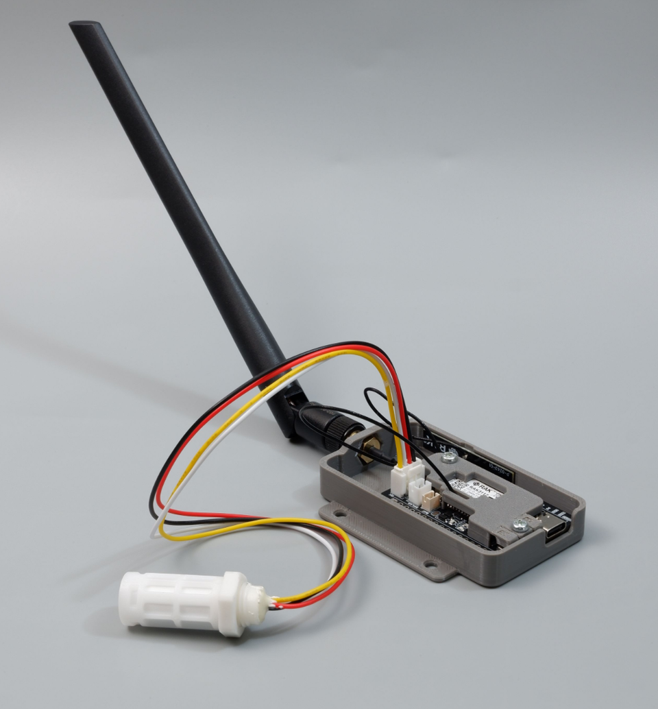
Figure: Cubicore Devboard mounted in an enclosure with an external 915 MHz antenna and a wired SHT30 temperature and humidity sensor probe.
The Sensirion SHT30 is an industry-standard, high-precision digital temperature and relative humidity sensor widely used in IoT weather stations, greenhouse monitoring, smart agriculture, and cold chain tracking.
Available as a plug-and-play Grove / Qwiic breakout module, the SHT30 interfaces with the Cubicore Devboard over the standard I2C protocol through the dedicated onboard Grove I2C Port (J6).
Sensor Specifications:
- Default I2C Address:
0x44(7-bit address whenADDRis connected to GND or floating;0x45whenADDRis pulled HIGH to 3.3V) - Temperature Range & Accuracy: -40°C to +125°C (±0.2°C typical)
- Relative Humidity Range & Accuracy: 0% to 100% RH (±2% RH typical)
- Operating Voltage: 2.4V to 5.5V (powered safely from the Devboard's regulated +3.3V system power rail)
- Communication Protocol: Standard I2C (supports 100 kHz standard mode and 400 kHz fast mode)
2. Hardware Connection & Grove Port Pinout
The Cubicore Devboard features a dedicated 4-pin Grove I2C connector (J6) wired directly to the primary ESP32-S3 hardware I2C bus.
+-------------------------------------------------------------+
|                      GROVE CONNECTOR (J6)                   |
|                                                             |
|       Pin 1: SCL  -----> Devboard GPIO 40                   |
|       Pin 2: SDA  -----> Devboard GPIO 9                    |
|       Pin 3: VCC  -----> +3.3V (Regulated System Rail)     |
|       Pin 4: GND  -----> Ground (GND)                       |
+-------------------------------------------------------------+
The ESP32-S3 on the Cubicore Devboard operates strictly on 3.3V logic levels. Power your SHT30 module from the +3.3V rail provided on the Grove connector. Do not apply 5V power or signals directly to Devboard GPIO 9 or Devboard GPIO 40.
Connecting the Sensor:
- Plug the 4-pin Grove cable into connector
J6on the Cubicore Devboard. - Connect the other end of the cable to your SHT30 sensor breakout.
- Connect the Devboard to your computer using a USB-C data cable.
3. Installing the Arduino Library
To communicate with the sensor, install the Adafruit SHT31 Library (which provides full native driver support for Sensirion SHT30, SHT31, and SHT35 sensors).
- In the Arduino IDE, navigate to Tools → Manage Libraries... (or press
Ctrl+Shift+I/Cmd+Shift+I). - Type
Adafruit SHT31into the search bar. - Locate Adafruit SHT31 Library by Adafruit and click Install.
- When prompted to install missing dependencies (such as Adafruit BusIO), select Install All.
4. Arduino Telemetry Sketch
The following sketch initializes the primary hardware I2C bus on the Grove port pins (GPIO 9 and GPIO 40), attempts to detect the SHT30 at its default address (0x44) with an automatic fallback to 0x45, and reads temperature and humidity every 2 seconds.
/*
 * Cubicore Devboard - SHT30 Temperature & Humidity Example
 * Board: ESP32S3 Dev Module
 * Sensor: Sensirion SHT30 connected to Grove I2C Port (J6)
 *
 * Pin Mapping:
 *   SDA -> Devboard GPIO 9
 *   SCL -> Devboard GPIO 40
 */

#include <Wire.h>
#include <Adafruit_SHT31.h>

// Onboard Grove I2C Pin Definitions
#define PIN_GROVE_SDA  9
#define PIN_GROVE_SCL  40

// Create sensor instance
Adafruit_SHT31 sht30 = Adafruit_SHT31();

void setup() {
  Serial.begin(115200);
  while (!Serial && millis() < 3000);

  Serial.println("\n==========================================");
  Serial.println("  Cubicore Devboard - SHT30 Environmental ");
  Serial.println("==========================================");

  // Initialize I2C peripheral on Grove port pins
  Wire.begin(PIN_GROVE_SDA, PIN_GROVE_SCL);

  // Initialize SHT30: try default address 0x44 first, then alternate address 0x45
  Serial.print(F("[INIT] Connecting to SHT30 at 0x44... "));
  if (!sht30.begin(0x44)) {
    Serial.println(F("Not found. Trying alternate address 0x45... "));
    if (!sht30.begin(0x45)) {
      Serial.println(F("[ERROR] SHT30 initialization failed!"));
      Serial.println(F("        1. Check Grove 4-pin cable connection."));
      Serial.println(F("        2. Verify 3.3V power to the sensor."));
      Serial.println(F("        3. Check I2C bus with an address scanner sketch."));
      while (1) {
        delay(1000);
      }
    }
  }

  Serial.println(F("SUCCESS."));
  Serial.println(F("[INFO] SHT30 sensor initialized and ready for readings.\n"));
}

void loop() {
  // Read temperature (°C) and relative humidity (%)
  float temperature = sht30.readTemperature();
  float humidity    = sht30.readHumidity();

  // Validate readings to ensure sensor has not disconnected
  if (!isnan(temperature) && !isnan(humidity)) {
    Serial.println("----------------------------------------");
    Serial.printf(" Temperature: %.2f °C\n", temperature);
    Serial.printf(" Humidity:    %.2f %%\n", humidity);
    Serial.println("----------------------------------------");
  } else {
    Serial.println(F("[WARN] Failed to read data from SHT30 sensor."));
  }

  delay(2000); // Sample every 2 seconds
}
5. Expected Serial Monitor Output
Open the Arduino Serial Monitor (Tools → Serial Monitor) and set the baud rate to 115200. You should see the initialization message followed by live environmental telemetry:
==========================================
  Cubicore Devboard - SHT30 Environmental
==========================================
[INIT] Connecting to SHT30 at 0x44... SUCCESS.
[INFO] SHT30 sensor initialized and ready for readings.

----------------------------------------
 Temperature: 25.42 °C
 Humidity:    61.85 %
----------------------------------------
----------------------------------------
 Temperature: 25.45 °C
 Humidity:    61.80 %
----------------------------------------
6. LoRaWAN Uplink Integration (RadioLib + TTN)
To convert this bench test into a field-deployed IoT node, you can transmit the SHT30 temperature and humidity data over long range to The Things Network (TTN) using the Devboard's onboard Semtech SX1262 transceiver.
Payload Packing Architecture
LoRaWAN duty-cycle regulations require packets to be as small as possible. Instead of sending raw text strings (e.g., "Temp: 25.42" which consumes 12 bytes), we multiply floats by 100 to preserve two decimal places and pack the integers into 6 binary bytes:
+---------------------+---------------------+---------------------+
| Packet Counter (2B) |   Temperature (2B)  |    Humidity (2B)    |
|   bytes[0] - [1]    |    bytes[2] - [3]   |    bytes[4] - [5]   |
+---------------------+---------------------+---------------------+
Full LoRaWAN Uplink Sketch (RadioLib)
This sketch uses the RadioLib library for the SX1262 radio and the ESP32's built-in Preferences.h library for session persistence (restoring the connection on reboot without re-joining).
/*
 * Cubicore Devboard - LoRaWAN SHT30 Environmental Node
 * Board: ESP32S3 Dev Module
 * Sensor: Sensirion SHT30 on Grove I2C (GPIO 9 = SDA, GPIO 40 = SCL)
 */

#include <RadioLib.h>
#include <SPI.h>
#include <Wire.h>
#include <Adafruit_SHT31.h>
#include <Preferences.h>

// ========================================================
// ⬇️ PASTE YOUR TTN KEYS HERE (MSB / C-Array format) ⬇️
// ========================================================
uint64_t joinEUI = 0x0000000000000000;
uint64_t devEUI  = 0x70B3D57ED007940B; // Replace with your DevEUI
uint8_t  appKey[] = { 0xB0, 0x7B, 0x60, 0xC1, 0x7E, 0xD0, 0x58, 0xFE, 0x8D, 0x3B, 0x76, 0x54, 0x10, 0x63, 0xD0, 0xB1 };
uint8_t  nwkKey[] = { 0xB0, 0x7B, 0x60, 0xC1, 0x7E, 0xD0, 0x58, 0xFE, 0x8D, 0x3B, 0x76, 0x54, 0x10, 0x63, 0xD0, 0xB1 };
// ========================================================

// SX1262 Pin Definitions for Cubicore Devboard
#define LORA_NSS   7
#define LORA_DIO1  47
#define LORA_RESET 8
#define LORA_BUSY  48
#define LORA_SCK   5
#define LORA_MISO  3
#define LORA_MOSI  6

// Sensor & LED Pins
#define PIN_GROVE_SDA  9
#define PIN_GROVE_SCL  40
#define PIN_LED_BLUE   45
#define PIN_LED_GREEN  46

SPIClass loraSPI(FSPI);
Module* loraMod = new Module(LORA_NSS, LORA_DIO1, LORA_RESET, LORA_BUSY, loraSPI);
SX1262 radio(loraMod);

// Frequency plan: AS923 Group 3 (Change to US915, EU868, etc. if required)
LoRaWANNode node(&radio, &AS923_3);

Adafruit_SHT31 sht30 = Adafruit_SHT31();
Preferences prefs;

#define NONCES_BUF_SIZE   RADIOLIB_LORAWAN_NONCES_BUF_SIZE
#define SESSION_BUF_SIZE  RADIOLIB_LORAWAN_SESSION_BUF_SIZE

const bool FORCE_FRESH_JOIN = false;

void handlePreferences() {
  prefs.begin("lorawan", false);

  if (FORCE_FRESH_JOIN) {
    Serial.println(F("[NVS] FORCE_FRESH_JOIN enabled. Wiping old session..."));
    prefs.clear();
  }

  // Restore session from NVS Flash
  if (prefs.isKey("nonces") && prefs.isKey("session")) {
    Serial.println(F("[NVS] Restoring saved session from Flash..."));
    uint8_t noncesBuf[NONCES_BUF_SIZE];
    uint8_t sessionBuf[SESSION_BUF_SIZE];
    prefs.getBytes("nonces", noncesBuf, NONCES_BUF_SIZE);
    prefs.getBytes("session", sessionBuf, SESSION_BUF_SIZE);
    node.setBufferNonces(noncesBuf);
    node.setBufferSession(sessionBuf);
    node.activateOTAA();
  }

  // Perform OTAA Join if no session exists
  if (!node.isActivated()) {
    Serial.println(F("[NETWORK] No active session. Starting OTAA Join..."));
    int attempt = 1;
    while (!node.isActivated() && attempt <= 5) {
      Serial.printf("[NETWORK] OTAA Join Attempt %d of 5... ", attempt);
      digitalWrite(PIN_LED_BLUE, HIGH);
      int16_t joinState = node.activateOTAA();
      digitalWrite(PIN_LED_BLUE, LOW);

      if (joinState == RADIOLIB_LORAWAN_NEW_SESSION) {
        Serial.println(F("SUCCESS!"));
        prefs.putBytes("nonces", node.getBufferNonces(), NONCES_BUF_SIZE);
        prefs.putBytes("session", node.getBufferSession(), SESSION_BUF_SIZE);
        Serial.println(F("[NVS] New session cached to Flash."));
        break;
      } else {
        Serial.printf("FAILED (Error: %d). Retrying in 5s...\n", joinState);
        delay(5000);
        attempt++;
      }
    }
  } else {
    Serial.println(F("[NVS] Session restored successfully! Ready for uplinks."));
  }
  prefs.end();

  if (!node.isActivated()) {
    Serial.println(F("\n[HALT] OTAA Join failed. Check gateway, antenna, and TTN keys."));
    while (true) {
      digitalWrite(PIN_LED_BLUE, !digitalRead(PIN_LED_BLUE));
      delay(250);
    }
  }
}

void setup() {
  Serial.begin(115200);
  while (!Serial && millis() < 3000);

  pinMode(PIN_LED_BLUE, OUTPUT);
  pinMode(PIN_LED_GREEN, OUTPUT);
  digitalWrite(PIN_LED_BLUE, LOW);
  digitalWrite(PIN_LED_GREEN, LOW);

  // Initialize SHT30 I2C
  Wire.begin(PIN_GROVE_SDA, PIN_GROVE_SCL);
  Serial.print(F("[SENSOR] SHT30 Check: "));
  if (!sht30.begin(0x44) && !sht30.begin(0x45)) {
    Serial.println(F("NOT FOUND! Check wiring."));
  } else {
    Serial.println(F("FOUND."));
  }

  // Initialize SX1262 LoRa Radio
  loraSPI.begin(LORA_SCK, LORA_MISO, LORA_MOSI, LORA_NSS);
  radio.begin();
  radio.setTCXO(1.8);
  radio.setDio2AsRfSwitch(true);

  node.beginOTAA(joinEUI, devEUI, nwkKey, appKey);

  // Dual-channel gateway compatibility (e.g. Gateway Pocket / Gateway Hub)
  node.setADR(false);
  node.setDatarate(2); // DR2 / SF10

  handlePreferences();
}

void loop() {
  static uint16_t packetCounter = 0;
  static unsigned long lastUplinkTime = 0;

  // Send uplink every 30 seconds
  if (millis() - lastUplinkTime > 30000 || lastUplinkTime == 0) {
    lastUplinkTime = millis();
    packetCounter++;

    float t = sht30.readTemperature();
    float h = sht30.readHumidity();

    int16_t tempScaled = isnan(t) ? 0x7FFF : (int16_t)(t * 100.0f);
    uint16_t humScaled = isnan(h) ? 0xFFFF : (uint16_t)(h * 100.0f);

    // Pack into 6-byte binary payload
    uint8_t payload[6];
    payload[0] = (packetCounter >> 8) & 0xFF;
    payload[1] = packetCounter & 0xFF;
    payload[2] = (tempScaled >> 8) & 0xFF;
    payload[3] = tempScaled & 0xFF;
    payload[4] = (humScaled >> 8) & 0xFF;
    payload[5] = humScaled & 0xFF;

    Serial.printf("\n[UPLINK] Packet #%u | Temp: %.2f °C | Hum: %.2f %%\n", packetCounter, t, h);

    digitalWrite(PIN_LED_BLUE, HIGH);
    int16_t state = node.sendReceive(payload, sizeof(payload), 1);
    digitalWrite(PIN_LED_BLUE, LOW);

    if (state == RADIOLIB_ERR_NONE || state > 0) {
      Serial.println(F("[UPLINK] Transmission SUCCESS."));
      digitalWrite(PIN_LED_GREEN, HIGH);
      delay(150);
      digitalWrite(PIN_LED_GREEN, LOW);

      // Save updated frame counter to NVS
      prefs.begin("lorawan", false);
      prefs.putBytes("session", node.getBufferSession(), SESSION_BUF_SIZE);
      prefs.end();
    } else {
      Serial.printf("[UPLINK] Transmission FAILED (Error: %d)\n", state);
    }
  }
}
TTN JavaScript Payload Decoder
In the TTN Console under Payload formatters → Uplink, select Custom Javascript formatter and paste the decoder below:
function decodeUplink(input) {
  var bytes = input.bytes;

  if (bytes.length < 6) {
    return { errors: ["Invalid payload length"] };
  }

  // 1. Packet Counter
  var counter = (bytes[0] << 8) | bytes[1];

  // 2. Temperature (handles negative values)
  var rawTemp = (bytes[2] << 8) | bytes[3];
  if (rawTemp & 0x8000) rawTemp -= 0x10000;
  var temperature = rawTemp / 100.0;

  // 3. Relative Humidity
  var rawHum = (bytes[4] << 8) | bytes[5];
  var humidity = rawHum / 100.0;

  return {
    data: {
      packet_counter: counter,
      temperature_c: temperature,
      humidity_rh: humidity
    }
  };
}
Expected JSON in TTN Live Data:
{
  "packet_counter": 1,
  "temperature_c": 25.42,
  "humidity_rh": 61.85
}
7. Troubleshooting & Diagnostics
| Symptom | Probable Cause | Recommended Fix |
|---|---|---|
[ERROR] SHT30 initialization failed! | Sensor not seated firmly or cable is loose. | Re-seat the Grove connector into port J6. Ensure the Grove latch clicks securely. |
Sensor found at 0x45 instead of 0x44 | The breakout board's ADDR pin is pulled HIGH. | Normal behavior for breakouts configured with address pin HIGH. The sketch automatically detects and supports 0x45. |
Serial prints [WARN] Failed to read data | Communication timeout or transient I2C bus error. | Check cable integrity and verify no high-current inductive loads (motors/relays) are injecting noise onto the I2C lines. |
| Device not detected at all | Grove port misassigned or I2C bus locked. | Verify that your sketch uses Wire.begin(9, 40) and not default ESP32 pins (21, 22). Refer to Chapter 4: Peripherals and I2C for the I2C bus scanner sketch. |
| LoRaWAN OTAA Join Fails (Error -1110 / Timeout) | Keys in LSB format, antenna not attached, or gateway out of range. | Confirm the RP-SMA antenna is connected. Ensure DevEUI and AppKey are in MSB format. Refer to Chapter 6: Joining a LoRaWAN Network for step-by-step key provisioning. |
8. Next Steps
- Deep Sleep Power Optimization:
Learn how to power down external I2C sensors and run the Devboard on battery for years in Chapter 8: Power and Battery Optimization. - Direct Point-to-Point Node Communications:
Learn how to transmit sensor telemetry directly between two Devboard nodes without a gateway in Chapter 7: LoRa P2P Communication.