MQ-2 Gas and Smoke Sensor with Cubicore Devboard
Applicable to the Cubicore Devboard (ESP32-S3 + SX1262 on RAK3112 module).
The Cubicore Devboard uses a 1:1 direct mapping between its physical silkscreen labels and ESP32-S3 GPIO numbers. In this guide, all references formatted as Devboard GPIO X (such as Devboard GPIO 14 and Devboard GPIO 21) directly correspond to the physical silkscreen labels on the board headers and the numeric pin definitions in Arduino IDE sketches.
1. Introduction & Sensor Overview
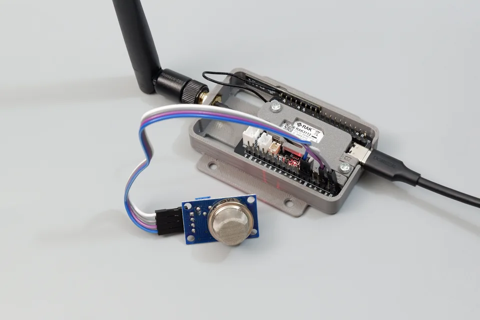
Figure: Cubicore Devboard mounted in its enclosure with an external 915 MHz antenna, wired to an MQ-2 combustible gas and smoke sensor breakout module.
The MQ-2 is an electro-chemical metal oxide semiconductor (MOS) gas sensor widely used in home safety, industrial monitoring, and fire alarm systems. It provides broad-spectrum detection for combustible and flammable gases, including:
- LPG (Liquid Petroleum Gas)
- Propane & Butane
- Methane (CH₄) / Natural Gas
- Hydrogen (H₂)
- Alcohol & Ethanol Vapors
- Combustion Smoke
The sensor contains an internal micro-ceramic heating tube and a Tin Dioxide (SnO₂) sensitive layer. In clean ambient air, SnO₂ exhibits high electrical resistance. When combustible gases or smoke molecules come into contact with the heated sensing layer, the gas molecules undergo oxidation, releasing electrons back into the semiconductor matrix. This causes the electrical resistance of the sensor to drop in direct proportion to the concentration of gas in the surrounding air.
Sensor Specifications:
- Sensing Element: Tin Dioxide (SnO₂) MOS layer with internal nichrome heater
- Target Gases: Combustible gases (LPG, propane, methane, butane, hydrogen), alcohol vapors, and smoke
- Concentration Detection Range:
- LPG & Propane: 200 ppm to 5,000 ppm
- Methane & Natural Gas: 5,000 ppm to 20,000 ppm
- Hydrogen: 300 ppm to 5,000 ppm
- Smoke: Qualitative detection
- Output Interfaces: Dual output — Analog voltage (
AD) and Digital threshold trigger (D0) - Heater Operating Power: ~800 mW to 900 mW (~150 mA to 180 mA at 5V)
- Preheating Stabilization Time: Minimum 20 to 30 seconds upon power-up (24 to 48 hours for initial factory burn-in)
2. Module Pinout & Onboard Controls
The standard 4-pin MQ-2 breakout module includes an integrated LM393 dual comparator circuit, two status LEDs, and a rear sensitivity adjustment potentiometer:
       MQ-2 Breakout Module (Front & Back Overview)
      +-----------------------------------------------+
      |   [ O ] Round Metal Mesh Sensor Element       |
      |                                               |
      |   [PWR LED]                  [ALARM LED]      |
      |                                               |
      |        +-----------------------------+        |
      |        |  ( + ) Rear Sensitivity Pot |        |
      |        +-----------------------------+        |
      |                                               |
      |     AD         D0          GND         VCC    |
      +------+----------+-----------+-----------+-----+
             |          |           |           |
             |          |           |           +--> Power Supply (3.3V or 5V)
             |          |           +--------------> Ground (GND)
             |          +--------------------------> Digital Threshold Trigger (D0)
             +-------------------------------------> Analog Voltage Output (AD / A0)
Module Interface Pins:
| Pin Label | Function | Type | Description |
|---|---|---|---|
VCC | Power Supply | Power | Connect to 3V3 for safe prototyping, or external regulated 5V (see voltage safety section). |
GND | Ground | Power | System ground reference. Connect to Devboard GND. |
D0 | Digital Output | Digital Out | Active LOW output driven by the onboard LM393 comparator. Flips from HIGH to LOW when gas exceeds the potentiometer threshold. |
AD | Analog Output | Analog Out | Outputs a continuous analog voltage (0V to VCC) proportional to detected gas concentration. |
The Rear Trimpot & Status LEDs:
- Sensitivity Potentiometer: A multi-turn or single-turn trimmer potentiometer on the back of the module. Rotating the pot adjusts the reference threshold voltage fed into the LM393 comparator. This allows you to set the exact gas or smoke concentration at which
D0triggers an alarm. - Power LED: Illuminates steadily whenever the module is receiving power.
- Alarm / Digital LED: Illuminates when detected gas concentration crosses the potentiometer threshold (when
D0goes LOW).
Why is the alarm LED stuck ON in clean air at power-up?
When the MQ-2 is cold, moisture and ambient contaminants absorbed on the chemical Tin Dioxide (SnO₂) layer cause its internal resistance to be very low. In clean room air right after power-on, the analog output sits abnormally high (between 2400 mV and 2900 mV).
Because this initial cold-start voltage exceeds the maximum reference voltage of the onboard LM393 comparator (typically ~1.8V to 2.2V), the comparator is overwhelmed and latches into a continuous alarm state (D0 = LOW, Alarm LED ON). Turning the potentiometer at this stage will appear to do nothing.
What you must do:
- Wait 3 to 5 minutes: Keep the sensor powered on. Touch the round metal mesh—it will feel gently warm as the internal heater bakes off surface moisture.
- Watch the voltage drop: In the Serial Monitor, observe the analog voltage steadily fall from ~2500 mV down towards its true clean-air baseline (typically 300 mV to 800 mV).
- Multi-turn Trimpot (15–25 full rotations): The blue potentiometer on most modules is a precision multi-turn trimmer (Bourns 3296 style). A single half-turn only adjusts the threshold by a few millivolts. Once the voltage drops below 1000 mV, you may need to turn the brass screw 10 to 20 full rotations counter-clockwise to turn the Alarm LED off.
3. Hardware Interfacing & 3.3V Logic Safety
The ESP32-S3 microcontroller on the Cubicore Devboard operates strictly on 3.3V logic levels (maximum allowable GPIO input voltage is 3.6V).
- Direct Devboard Connection (Recommended for Prototyping):
Powering the MQ-2 module directly from the Devboard's3V3rail is safe for bothADandD0, as output voltages will never exceed 3.3V. While the internal heating element will run at reduced temperature, it is fully adequate for threshold testing, smoke detection demonstrations, and bench prototyping. - External 5V Power (Maximum Sensitivity):
If powering the MQ-2 from an external 5V power supply for maximum sensitivity, theADandD0lines will output up to 5V. You must use a resistor voltage divider or logic level shifter to attenuate the signals to 3.3V before connecting them to the ESP32-S3.
Recommended Wiring (Direct 3.3V Prototyping)
Connect the MQ-2 breakout module to the Cubicore Devboard's Header J1 as shown below:
+-----------------------------------------------------------------+
|                  CUBICORE DEVBOARD (HEADER J1)                  |
|                                                                 |
|       Pin 2:  3V3     -----> MQ-2 VCC (Regulated +3.3V Rail)    |
|       Pin 13: GPIO14  -----> MQ-2 AD  (Analog Input - AIN1)     |
|       Pin 16: GPIO21  -----> MQ-2 D0  (Digital Alarm Input)     |
|       Pin 18: GND     -----> MQ-2 GND (System Ground)           |
+-----------------------------------------------------------------+
| MQ-2 Module Pin | Wire Color | Cubicore Devboard Pin | Pin Function / Notes |
|---|---|---|---|
VCC | Red | Header J1, Pin 2 (3V3) | +3.3V Regulated System Power Rail |
GND | Black | Header J1, Pin 18 (GND) | System Ground Reference |
AD (Analog) | Blue or Green | Header J1, Pin 13 (GPIO14) | ADC Input (AIN1 / Analog Channel) |
D0 (Digital) | Yellow | Header J1, Pin 16 (GPIO21) | Digital Input with Hardware Interrupt support |
4. Arduino Telemetry & Alarm Sketch
The following sketch performs two simultaneous monitoring tasks:
- Continuous Analog Sampling: Reads the raw voltage from
ADonDevboard GPIO 14using the ESP32-S3 calibrated ADC (analogReadMilliVolts()) to track subtle gas trends. - Instant Digital Alarm Interrupt: Attaches a hardware falling-edge interrupt to
D0onDevboard GPIO 21to immediately detect when gas concentration exceeds the potentiometer threshold.
/*
 * Cubicore Devboard - MQ-2 Gas and Smoke Sensor Example
 * Board: ESP32S3 Dev Module
 * Sensor: MQ-2 Flammable Gas & Smoke Breakout Module
 *
 * Hardware Wiring:
 *   MQ-2 VCC -> Devboard Header J1, Pin 2 (3V3)
 *   MQ-2 GND -> Devboard Header J1, Pin 18 (GND)
 *   MQ-2 AD  -> Devboard Header J1, Pin 13 (Devboard GPIO 14 / AIN1)
 *   MQ-2 D0  -> Devboard Header J1, Pin 16 (Devboard GPIO 21)
 */

// Pin Definitions
#define PIN_MQ2_ANALOG   14   // Devboard GPIO 14 (Analog In AIN1)
#define PIN_MQ2_DIGITAL  21   // Devboard GPIO 21 (Digital Alarm Pin)

// Volatile flag for hardware interrupt tracking
volatile bool gasAlarmTriggered = false;

// Interrupt Service Routine (ISR) triggered when D0 goes LOW
void IRAM_ATTR onGasAlarmISR() {
  gasAlarmTriggered = true;
}

void setup() {
  Serial.begin(115200);
  while (!Serial && millis() < 3000);

  Serial.println("\n==========================================");
  Serial.println("  Cubicore Devboard - MQ-2 Gas Monitor    ");
  Serial.println("==========================================");

  // Configure digital alarm input with internal pull-up
  pinMode(PIN_MQ2_DIGITAL, INPUT_PULLUP);

  // Attach hardware interrupt on falling edge (Active LOW trigger)
  attachInterrupt(digitalPinToInterrupt(PIN_MQ2_DIGITAL), onGasAlarmISR, FALLING);

  // Configure ADC resolution (12-bit: 0 - 4095)
  analogReadResolution(12);

  // Pre-heating Warm-Up Cycle
  // The internal SnO2 sensor element requires thermal stabilization
  Serial.println(F("[INIT] Warming up MQ-2 sensor element..."));
  for (int sec = 20; sec > 0; sec--) {
    Serial.printf("[WARMUP] Stabilizing... %d seconds remaining\r", sec);
    delay(1000);
  }
  Serial.println(F("\n[INIT] Sensor warm-up complete. Monitoring active.\n"));
}

void loop() {
  // Read calibrated voltage from the analog pin in millivolts (mV)
  uint32_t analogMilliVolts = analogReadMilliVolts(PIN_MQ2_ANALOG);

  // Read instantaneous digital comparator state (LOW = Alarm, HIGH = Normal)
  int digitalState = digitalRead(PIN_MQ2_DIGITAL);

  // Check if hardware interrupt was triggered
  if (gasAlarmTriggered || digitalState == LOW) {
    Serial.println("************************************************");
    Serial.println(" [ALERT] GAS / SMOKE THRESHOLD EXCEEDED!       ");
    Serial.printf (" [ALERT] Analog Voltage: %u mV | Digital: LOW  \n", analogMilliVolts);
    Serial.println("************************************************");

    // Reset interrupt flag after reporting
    gasAlarmTriggered = false;
  } else {
    // Normal ambient telemetry
    Serial.printf("[STATUS] Normal | Voltage: %4u mV | Alarm: IDLE\n", analogMilliVolts);
  }

  delay(1500); // Sample every 1.5 seconds
}
5. Calibrating the Onboard Potentiometer
The onboard potentiometer sets the trigger trip-point for the digital pin (D0) and the onboard alarm LED:
-
Power and Warm Up (Crucial):
Power the Cubicore Devboard with the MQ-2 sensor connected in a clean, well-ventilated room. Allow the sensor to warm up for 3 to 5 minutes until the metal housing feels gently warm to the touch.Check Voltage in Serial Monitor Before Adjusting PotDo not attempt to adjust the potentiometer while the analog voltage is sitting above 1000 mV. Wait until you see the voltage drop and stabilize (typically between 300 mV and 800 mV in clean air).
-
Locate the Trimmer Potentiometer:
On the back of the MQ-2 module, locate the small blue potentiometer with a brass screw top. Note that most modules use a 25-turn precision trimmer (Bourns 3296 style) which requires many full rotations to sweep through its voltage range.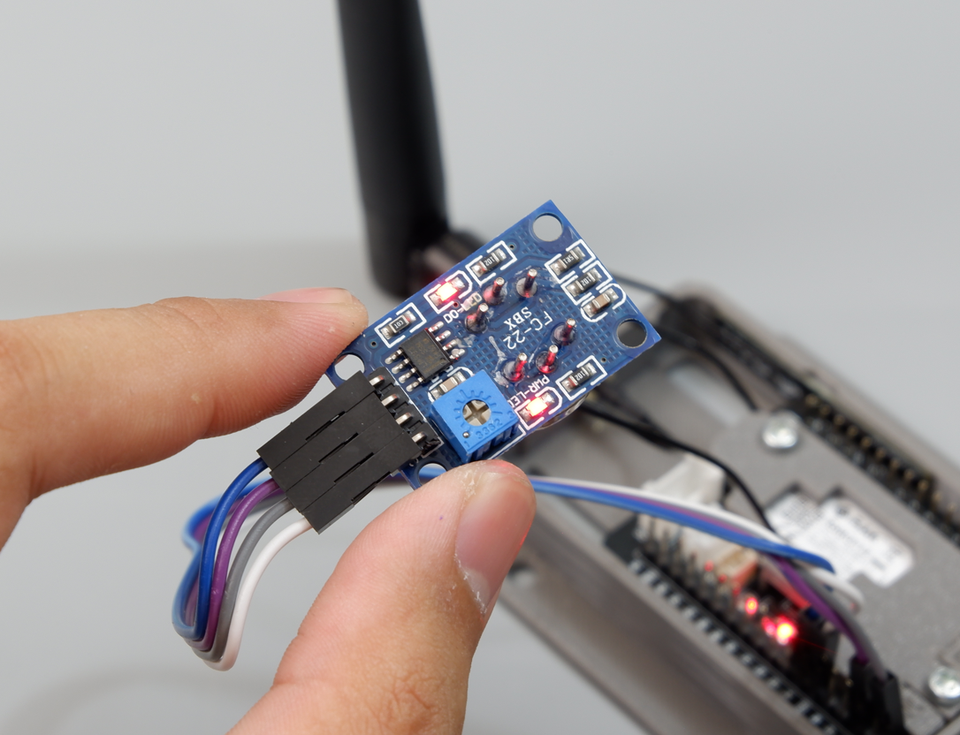
Figure: Rear controls of the MQ-2 breakout module showing the blue trimmer potentiometer, the illuminated red PWR-LED (power), and the red DO-LED (digital alarm indicator).
-
Set the Baseline Trip Point:
- If the onboard Alarm LED is lit after warm-up: turn the brass screw counter-clockwise with a small flathead screwdriver. You may need to rotate it 10 to 20 full turns until the LED just turns OFF.
- If the Alarm LED is OFF: turn the screw clockwise until the LED just illuminates, then back it off counter-clockwise 1 to 2 turns until the LED turns OFF.
-
Test the Response:
Briefly introduce a small gas source near the round mesh face (for example, press the release valve of an unlit butane lighter for 1 second, or blow smoke from an extinguished match):- The onboard Alarm LED should instantly illuminate.
- The Serial Monitor will immediately print the
[ALERT] GAS / SMOKE THRESHOLD EXCEEDED!message. - Once the gas clears, the LED turns off and the output returns to
[STATUS] Normal.
6. Expected Serial Monitor Output
Open the Arduino Serial Monitor (Tools → Serial Monitor) and set the baud rate to 115200. You should see the warm-up countdown followed by real-time voltage monitoring and alert triggers:
==========================================
  Cubicore Devboard - MQ-2 Gas Monitor
==========================================
[INIT] Warming up MQ-2 sensor element...
[INIT] Sensor warm-up complete. Monitoring active.

[STATUS] Normal | Voltage:  342 mV | Alarm: IDLE
[STATUS] Normal | Voltage:  345 mV | Alarm: IDLE
[STATUS] Normal | Voltage:  340 mV | Alarm: IDLE
************************************************
 [ALERT] GAS / SMOKE THRESHOLD EXCEEDED!
 [ALERT] Analog Voltage: 1845 mV | Digital: LOW
************************************************
************************************************
 [ALERT] GAS / SMOKE THRESHOLD EXCEEDED!
 [ALERT] Analog Voltage: 2110 mV | Digital: LOW
************************************************
[STATUS] Normal | Voltage:  610 mV | Alarm: IDLE
[STATUS] Normal | Voltage:  355 mV | Alarm: IDLE
7. LoRaWAN Uplink Integration (RadioLib + TTN)
To deploy the MQ-2 as a wireless industrial gas leak or fire alarm node, you can broadcast its analog concentration and digital trip status directly to The Things Network (TTN) using the Devboard's Semtech SX1262 transceiver.
Payload Packing Architecture
To minimize airtime and comply with fair-access regulations, we pack the telemetry into a compact 6-byte binary payload:
+---------------------+---------------------+------------------+------------------+
| Packet Counter (2B) | Analog Voltage (2B) |  Alarm State (1B)| Reserved/Pad (1B)|
|   bytes[0] - [1]    |    bytes[2] - [3]   |     bytes[4]     |     bytes[5]     |
+---------------------+---------------------+------------------+------------------+
- Packet Counter: 16-bit integer (0–65535).
- Analog Voltage: 16-bit integer representing calibrated sensor voltage in millivolts (0 to 3300 mV).
- Alarm State: 8-bit flag (
0x01= Gas Alarm Active,0x00= Normal / Idle). - Reserved: 8-bit zero padding byte (
0x00).
Full LoRaWAN Uplink Sketch (RadioLib)
This sketch combines the MQ-2 analog ADC and digital alarm monitoring with RadioLib and Preferences.h for NVS session caching.
/*
 * Cubicore Devboard - LoRaWAN MQ-2 Gas & Smoke Alarm Node
 * Board: ESP32S3 Dev Module
 * Sensor: MQ-2 Breakout Module on GPIO 14 (Analog) and GPIO 21 (Digital)
 */

#include <RadioLib.h>
#include <SPI.h>
#include <Preferences.h>

// ========================================================
// ⬇️ PASTE YOUR TTN KEYS HERE (MSB / C-Array format) ⬇️
// ========================================================
uint64_t joinEUI = 0x0000000000000000;
uint64_t devEUI  = 0x70B3D57ED007940B; // Replace with your DevEUI
uint8_t  appKey[] = { 0xB0, 0x7B, 0x60, 0xC1, 0x7E, 0xD0, 0x58, 0xFE, 0x8D, 0x3B, 0x76, 0x54, 0x10, 0x63, 0xD0, 0xB1 };
uint8_t  nwkKey[] = { 0xB0, 0x7B, 0x60, 0xC1, 0x7E, 0xD0, 0x58, 0xFE, 0x8D, 0x3B, 0x76, 0x54, 0x10, 0x63, 0xD0, 0xB1 };
// ========================================================

// SX1262 Pin Definitions for Cubicore Devboard
#define LORA_NSS   7
#define LORA_DIO1  47
#define LORA_RESET 8
#define LORA_BUSY  48
#define LORA_SCK   5
#define LORA_MISO  3
#define LORA_MOSI  6

// MQ-2 Sensor & LED Pins
#define PIN_MQ2_ANALOG   14   // Devboard GPIO 14 (AIN1)
#define PIN_MQ2_DIGITAL  21   // Devboard GPIO 21 (Alarm Input)
#define PIN_LED_BLUE     45
#define PIN_LED_GREEN    46

SPIClass loraSPI(FSPI);
Module* loraMod = new Module(LORA_NSS, LORA_DIO1, LORA_RESET, LORA_BUSY, loraSPI);
SX1262 radio(loraMod);

// Regional plan: AS923 Group 3 (Change to US915, EU868, etc. if required)
LoRaWANNode node(&radio, &AS923_3);
Preferences prefs;

#define NONCES_BUF_SIZE   RADIOLIB_LORAWAN_NONCES_BUF_SIZE
#define SESSION_BUF_SIZE  RADIOLIB_LORAWAN_SESSION_BUF_SIZE

const bool FORCE_FRESH_JOIN = false;

void handlePreferences() {
  prefs.begin("lorawan", false);

  if (FORCE_FRESH_JOIN) {
    Serial.println(F("[NVS] FORCE_FRESH_JOIN enabled. Wiping old session..."));
    prefs.clear();
  }

  // Restore session from NVS Flash
  if (prefs.isKey("nonces") && prefs.isKey("session")) {
    Serial.println(F("[NVS] Restoring saved session from Flash..."));
    uint8_t noncesBuf[NONCES_BUF_SIZE];
    uint8_t sessionBuf[SESSION_BUF_SIZE];
    prefs.getBytes("nonces", noncesBuf, NONCES_BUF_SIZE);
    prefs.getBytes("session", sessionBuf, SESSION_BUF_SIZE);
    node.setBufferNonces(noncesBuf);
    node.setBufferSession(sessionBuf);
    node.activateOTAA();
  }

  // Perform OTAA Join if no session exists
  if (!node.isActivated()) {
    Serial.println(F("[NETWORK] No active session. Starting OTAA Join..."));
    int attempt = 1;
    while (!node.isActivated() && attempt <= 5) {
      Serial.printf("[NETWORK] OTAA Join Attempt %d of 5... ", attempt);
      digitalWrite(PIN_LED_BLUE, HIGH);
      int16_t joinState = node.activateOTAA();
      digitalWrite(PIN_LED_BLUE, LOW);

      if (joinState == RADIOLIB_LORAWAN_NEW_SESSION) {
        Serial.println(F("SUCCESS!"));
        prefs.putBytes("nonces", node.getBufferNonces(), NONCES_BUF_SIZE);
        prefs.putBytes("session", node.getBufferSession(), SESSION_BUF_SIZE);
        Serial.println(F("[NVS] New session cached to Flash."));
        break;
      } else {
        Serial.printf("FAILED (Error: %d). Retrying in 5s...\n", joinState);
        delay(5000);
        attempt++;
      }
    }
  } else {
    Serial.println(F("[NVS] Session restored successfully! Ready for uplinks."));
  }
  prefs.end();

  if (!node.isActivated()) {
    Serial.println(F("\n[HALT] OTAA Join failed. Check gateway, antenna, and TTN keys."));
    while (true) {
      digitalWrite(PIN_LED_BLUE, !digitalRead(PIN_LED_BLUE));
      delay(250);
    }
  }
}

void setup() {
  Serial.begin(115200);
  while (!Serial && millis() < 3000);

  pinMode(PIN_LED_BLUE, OUTPUT);
  pinMode(PIN_LED_GREEN, OUTPUT);
  digitalWrite(PIN_LED_BLUE, LOW);
  digitalWrite(PIN_LED_GREEN, LOW);

  // Configure MQ-2 pins
  pinMode(PIN_MQ2_DIGITAL, INPUT_PULLUP);
  analogReadResolution(12);

  // Warm-up sensor
  Serial.println(F("[INIT] Warming up MQ-2 sensor element..."));
  for (int sec = 20; sec > 0; sec--) {
    Serial.printf("[WARMUP] Stabilizing... %d seconds remaining\r", sec);
    delay(1000);
  }
  Serial.println(F("\n[INIT] Warm-up complete."));

  // Initialize SX1262 LoRa Radio
  loraSPI.begin(LORA_SCK, LORA_MISO, LORA_MOSI, LORA_NSS);
  radio.begin();
  radio.setTCXO(1.8);
  radio.setDio2AsRfSwitch(true);

  node.beginOTAA(joinEUI, devEUI, nwkKey, appKey);

  // Dual-channel gateway settings
  node.setADR(false);
  node.setDatarate(2); // DR2 / SF10

  handlePreferences();
}

void loop() {
  static uint16_t packetCounter = 0;
  static unsigned long lastUplinkTime = 0;

  // Send periodic uplink every 30 seconds
  if (millis() - lastUplinkTime > 30000 || lastUplinkTime == 0) {
    lastUplinkTime = millis();
    packetCounter++;

    // Read analog millivolts and digital alarm state (LOW = Alarm)
    uint16_t voltageMv = (uint16_t)analogReadMilliVolts(PIN_MQ2_ANALOG);
    bool isAlarm = (digitalRead(PIN_MQ2_DIGITAL) == LOW);

    // Pack into 6-byte binary payload
    uint8_t payload[6];
    payload[0] = (packetCounter >> 8) & 0xFF;
    payload[1] = packetCounter & 0xFF;
    payload[2] = (voltageMv >> 8) & 0xFF;
    payload[3] = voltageMv & 0xFF;
    payload[4] = isAlarm ? 0x01 : 0x00;
    payload[5] = 0x00; // Reserved padding

    Serial.printf("\n[UPLINK] Packet #%u | Voltage: %u mV | Alarm: %s\n",
                  packetCounter, voltageMv, isAlarm ? "ACTIVE ALERT!" : "NORMAL");

    digitalWrite(PIN_LED_BLUE, HIGH);
    int16_t state = node.sendReceive(payload, sizeof(payload), 1);
    digitalWrite(PIN_LED_BLUE, LOW);

    if (state == RADIOLIB_ERR_NONE || state > 0) {
      Serial.println(F("[UPLINK] Transmission SUCCESS."));
      digitalWrite(PIN_LED_GREEN, HIGH);
      delay(150);
      digitalWrite(PIN_LED_GREEN, LOW);

      // Save updated frame counter to NVS
      prefs.begin("lorawan", false);
      prefs.putBytes("session", node.getBufferSession(), SESSION_BUF_SIZE);
      prefs.end();
    } else {
      Serial.printf("[UPLINK] Transmission FAILED (Error: %d)\n", state);
    }
  }
}
TTN JavaScript Payload Decoder
In the TTN Console under Payload formatters → Uplink, select Custom Javascript formatter and paste the decoder below:
function decodeUplink(input) {
  var bytes = input.bytes;

  if (bytes.length < 5) {
    return { errors: ["Invalid payload length"] };
  }

  // 1. Packet Counter
  var counter = (bytes[0] << 8) | bytes[1];

  // 2. Analog Voltage in Millivolts
  var voltageMv = (bytes[2] << 8) | bytes[3];

  // 3. Digital Alarm Status (0 = Normal, 1 = Alarm)
  var isAlarm = bytes[4] === 1;

  return {
    data: {
      packet_counter: counter,
      analog_voltage_mv: voltageMv,
      gas_alarm: isAlarm,
      status: isAlarm ? "ALERT: Gas/Smoke Detected!" : "NORMAL"
    }
  };
}
Expected JSON in TTN Live Data:
{
  "packet_counter": 1,
  "analog_voltage_mv": 345,
  "gas_alarm": false,
  "status": "NORMAL"
}
8. Troubleshooting & Diagnostics
| Symptom | Probable Cause | Recommended Fix |
|---|---|---|
| Alarm LED permanently ON at boot in clean air; turning pot does nothing | Cold-start moisture on SnO2 layer causes voltage to float above 2400 mV, exceeding the LM393 comparator reference threshold (~1.8V). | Wait 3 to 5 minutes for the internal heater to bake off moisture and allow the analog voltage to fall below 1000 mV in clean air. Then rotate the trimmer screw 10 to 20 full turns counter-clockwise until the LED turns off. |
| Sensor body feels warm/hot to the touch | Internal heating element is actively powered. | Normal behavior. The MQ-2 relies on an internal nichrome coil heater operating at ~300°C to activate the SnO2 layer. A warm metal mesh is required for proper operation. |
[ALERT] triggers continuously even after warm-up | Sensitivity potentiometer is set too sensitively. | Turn the rear potentiometer counter-clockwise 5–10 turns until the onboard Alarm LED turns off in clean air. |
| Sensor does not trigger when gas is introduced | Potentiometer threshold is set too high or warmup incomplete. | Allow at least 20–30 seconds for the heater to stabilize. Turn the potentiometer clockwise until the sensor triggers at your desired gas concentration. |
Analog voltage (AD) never changes | Jumper wire disconnected or wrong ADC channel. | Verify connection to Header J1, Pin 13 (GPIO14). In your sketch, ensure analogReadMilliVolts(14) is called. |
| Readings drift significantly over hours | Initial burn-in phase of new SnO2 sensor. | New MQ-2 sensors require a 24- to 48-hour continuous burn-in period to burn off protective factory coatings and stabilize the baseline resistance. |
| LoRaWAN OTAA Join Fails (Error -1110 / Timeout) | Keys in LSB format, antenna missing, or gateway out of range. | Confirm the external RP-SMA antenna is connected. Verify DevEUI and AppKey match TTN in MSB format. Refer to Chapter 6: Joining a LoRaWAN Network. |
9. Next Steps & IoT Integration
With the MQ-2 sensor operating on your Cubicore Devboard, you can integrate gas and smoke alerts into long-range IoT networks:
- Point-to-Point Industrial Alarms:
Transmit immediate gas threshold alerts to an off-grid Cubicore receiver or buzzer node using low-latency LoRa in Chapter 7: LoRa P2P Communication. - Power Management Considerations:
Because the internal MQ-2 heating coil draws ~150 mA continuously, it is not suitable for coin-cell or ultra-long sleep deployments without an external high-side MOSFET switch. Learn about power budgets and external power-gating in Chapter 8: Power and Battery Optimization.