DHT11 Temperature and Humidity Sensor with Cubicore Devboard
Applicable to the Cubicore Devboard (ESP32-S3 + SX1262 on RAK3112 module).
The Cubicore Devboard uses a 1:1 direct mapping between its physical silkscreen labels and ESP32-S3 GPIO numbers. In this guide, all references formatted as Devboard GPIO X (such as Devboard GPIO 21) directly correspond to the physical silkscreen labels on the board headers and the numeric pin definitions in Arduino IDE sketches.
1. Introduction & Sensor Overview
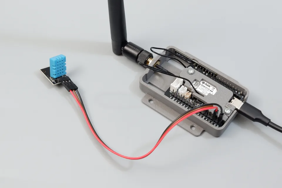
Figure: Cubicore Devboard mounted in its enclosure with an external 915 MHz antenna, connected via USB-C to a 3-pin DHT11 temperature and humidity sensor breakout module.
The DHT11 is an entry-level, composite digital temperature and humidity sensor widely used in basic environmental sensing, home automation, and educational prototyping. It integrates a capacitive humidity sensing component, an NTC negative temperature coefficient thermistor, and an internal 8-bit microcontroller that digitizes the analog readings and outputs them over a single-wire digital bus.
Unlike I2C sensors (such as the Sensirion SHT30) which require a dedicated two-wire bus (SDA and SCL), the DHT11 communicates using a custom single-bus (1-Wire) protocol. This protocol allows bidirectional communication between the ESP32-S3 microcontroller and the sensor over a single general-purpose input/output pin, saving valuable board I/O lines for additional peripherals.
Sensor Specifications:
- Communication Protocol: Proprietary single-bus (single-wire serial interface)
- Relative Humidity Range: 20% to 90% RH
- Humidity Accuracy: ±5% RH (Resolution: 1% RH)
- Temperature Range: 0°C to 50°C
- Temperature Accuracy: ±2°C (Resolution: 1°C)
- Operating Voltage: 3.3V to 5.5V DC (powered from the Devboard's regulated +3.3V system power rail)
- Operating Current: 0.5 mA to 2.5 mA during conversion (100 µA standby)
- Sampling Period: Minimum 1 to 2 seconds between consecutive readings
Comparing DHT11, DHT22, and SHT30
When selecting an environmental sensor for your IoT deployment, consider the trade-offs between precision, bus protocol, and power consumption:
| Feature / Metric | DHT11 (This Guide) | DHT22 / AM2302 | Sensirion SHT30 (Chapter 4 Example) |
|---|---|---|---|
| Interface Protocol | Single-Bus (1-Wire digital) | Single-Bus (1-Wire digital) | Standard I2C (Wire / Wire1) |
| Pins Required | 1 Digital GPIO + Power | 1 Digital GPIO + Power | 2 I2C Pins (SDA, SCL) + Power |
| Recommended Port | Header J1 (Devboard GPIO 21) | Header J1 (Devboard GPIO 21) | Dedicated Grove Port J6 (GPIO 9/40) |
| Humidity Range | 20% to 90% RH | 0% to 100% RH | 0% to 100% RH |
| Humidity Accuracy | ±5% RH | ±2% RH | ±2% RH |
| Temperature Range | 0°C to 50°C | -40°C to +80°C | -40°C to +125°C |
| Temperature Accuracy | ±2°C | ±0.5°C | ±0.2°C |
| Response Time | 6–10 seconds | 2 seconds | 8 seconds |
| Sampling Interval | ≥ 1–2 seconds | ≥ 2 seconds | Continuous / Instantaneous |
| Best For | Rapid low-cost prototyping, indoor bench tests | Hobby weather stations | High-precision agricultural & industrial IoT |
2. Hardware Connection & Wiring Pinout
The Cubicore Devboard exposes general-purpose I/O pins, power rails, and grounds across its two 18-pin expansion headers (J1 on the left and J2 on the right).
For single-bus communication, we recommend using Devboard GPIO 21 on Header J1 (Pin 16). It is positioned directly adjacent to the ground and battery pins on the lower edge of the board, simplifying breadboard and jumper wire routing.
+-------------------------------------------------------------+
|                  CUBICORE DEVBOARD (HEADER J1)              |
|                                                             |
|       Pin 2:  3V3     -----> +3.3V Regulated System Rail    |
|       Pin 16: GPIO21  -----> Devboard GPIO 21 (Data Line)   |
|       Pin 18: GND     -----> Ground (GND)                   |
+-------------------------------------------------------------+
The ESP32-S3 microcontroller on the Cubicore Devboard operates strictly on 3.3V logic levels (maximum allowable voltage is 3.6V). While the DHT11 hardware can physically accept 5V, powering the sensor from 5V causes its DATA line to output 5V logic pulses, which will permanently damage the ESP32-S3 GPIO pin.
Always connect the sensor VCC to the Devboard's +3.3V rail (3V3).
Sensor Hardware Variants
DHT11 sensors commonly come in two physical formats:
Variant A: 3-Pin Breakout Module (Recommended for Beginners)
Most pre-packaged DIY sensor kits provide the DHT11 mounted on a small 3-pin PCB. These breakout modules already include an onboard SMD 10 kΩ pull-up resistor between VCC and DATA, eliminating the need for external breadboard resistors.
| Breakout Pin Label | Wire Color | Cubicore Devboard Connection |
|---|---|---|
+ / VCC | Red | Header J1, Pin 2 (3V3) |
out / S / DAT | Yellow or Blue | Header J1, Pin 16 (GPIO21) |
- / GND | Black | Header J1, Pin 18 (GND) |
Variant B: 4-Pin Raw Sensor Package
Standalone DHT11 sensors feature a blue 4-pin rectangular package. The single-bus protocol requires an external pull-up resistor (typically 4.7 kΩ to 10 kΩ) connected between the sensor's VCC and DATA lines so the bus returns to a logic HIGH state when idle.
       Raw DHT11 Sensor (Front View)
          +---------------+
          |  [ # # # # ]  |
          |  [ # # # # ]  |
          +---------------+
             |   |   |   |
             1   2   3   4
             |   |   |   |
             |   |   |   +--> Pin 4: GND ------> Devboard Header J1, Pin 18 (GND)
             |   |   +------> Pin 3: NC -------> (No connection / Leave floating)
             |   +----------> Pin 2: DATA -----> Devboard Header J1, Pin 16 (GPIO21)
             |         |
             |         +----[ 10 kΩ Pull-Up Resistor ]
             |         |
             +---------+----> Pin 1: VCC ------> Devboard Header J1, Pin 2 (3V3)
| Sensor Pin # | Function | Connection Details |
|---|---|---|
| 1 | VCC | Connect to Header J1, Pin 2 (3V3). |
| 2 | DATA | Connect to Header J1, Pin 16 (GPIO21). Place a 10 kΩ resistor between Pin 1 and Pin 2. |
| 3 | NC | Not connected. Leave floating. |
| 4 | GND | Connect to Header J1, Pin 18 (GND) or Pin 1 (GND). |
3. Installing the Arduino Library
To decode the DHT11 single-bus timings and parity checks, install the official DHT sensor library by Adafruit:
- Open the Arduino IDE.
- Navigate to Tools → Manage Libraries... (or press
Ctrl+Shift+Ion Windows/Linux,Cmd+Shift+Ion macOS). - In the search box, enter
DHT sensor library. - Locate the library named DHT sensor library by Adafruit. Click Install.
- When prompted to install missing dependencies (such as Adafruit Unified Sensor), click Install All.
4. Arduino Telemetry Sketch
The following sketch initializes the sensor on Devboard GPIO 21, reads the relative humidity and ambient temperature, calculates the apparent Heat Index (feels-like temperature), and validates the integrity of each reading.
/*
 * Cubicore Devboard - DHT11 Temperature & Humidity Example
 * Board: ESP32S3 Dev Module
 * Sensor: DHT11 Digital Sensor (Single-Bus Interface)
 *
 * Hardware Wiring:
 *   DHT11 VCC   -> Devboard Header J1, Pin 2 (3V3)
 *   DHT11 DATA  -> Devboard Header J1, Pin 16 (Devboard GPIO 21)
 *   DHT11 GND   -> Devboard Header J1, Pin 18 (GND)
 *
 * Note: If using a bare 4-pin sensor, install a 10 kΩ pull-up
 * resistor between VCC (3.3V) and DATA (GPIO 21).
 */

#include "DHT.h"

// Define the single-bus data pin and sensor type
#define DHTPIN  21      // Devboard GPIO 21 (Header J1, Pin 16)
#define DHTTYPE DHT11   // Sensor model: DHT11

// Instantiate the DHT sensor object
DHT dht(DHTPIN, DHTTYPE);

void setup() {
  // Initialize primary USB serial port
  Serial.begin(115200);
  while (!Serial && millis() < 3000);

  Serial.println("\n==========================================");
  Serial.println("  Cubicore Devboard - DHT11 Environmental ");
  Serial.println("==========================================");
  Serial.println("[INIT] Initializing single-bus interface on GPIO 21...");

  // Start the DHT sensor
  dht.begin();

  Serial.println("[INIT] DHT11 driver active. Awaiting first conversion...\n");
  delay(1000);
}

void loop() {
  // The DHT11 requires at least 1-2 seconds between consecutive reads.
  // Reading faster than this will return stale or duplicate data.
  delay(2000);

  // Read relative humidity (percentage)
  float humidity = dht.readHumidity();

  // Read temperature as Celsius (the default)
  float tempC = dht.readTemperature();

  // Read temperature as Fahrenheit (isFahrenheit = true)
  float tempF = dht.readTemperature(true);

  // Validate telemetry to verify transmission integrity
  if (isnan(humidity) || isnan(tempC) || isnan(tempF)) {
    Serial.println(F("[WARN] Failed to read from DHT11 sensor!"));
    Serial.println(F("       1. Verify jumper wire connections on GPIO 21 and 3V3."));
    Serial.println(F("       2. Check pull-up resistor (10 kΩ between 3V3 and DATA)."));
    Serial.println(F("       3. Ensure sensor has finished initial power-on stabilization."));
    return;
  }

  // Compute Heat Index (perceived 'feels-like' temperature)
  float heatIndexC = dht.computeHeatIndex(tempC, humidity, false);
  float heatIndexF = dht.computeHeatIndex(tempF, humidity);

  // Print formatted telemetry stream
  Serial.println("----------------------------------------");
  Serial.printf(" Humidity:    %.1f %%\n", humidity);
  Serial.printf(" Temperature: %.1f °C  (%.1f °F)\n", tempC, tempF);
  Serial.printf(" Heat Index:  %.1f °C  (%.1f °F)\n", heatIndexC, heatIndexF);
  Serial.println("----------------------------------------");
}
5. Expected Serial Monitor Output
- Connect the Cubicore Devboard to your computer using a USB-C cable.
- In the Arduino IDE, verify your board and port selections:
- Board:
ESP32S3 Dev Module - Port: Select the COM / serial port corresponding to your Cubicore Devboard.
- Board:
- Click Upload (
Ctrl+U/Cmd+U). - Open the Serial Monitor (Tools → Serial Monitor) and set the baud rate to
115200.
You should observe the startup sequence followed by continuous environmental readings updated every two seconds:
==========================================
  Cubicore Devboard - DHT11 Environmental
==========================================
[INIT] Initializing single-bus interface on GPIO 21...
[INIT] DHT11 driver active. Awaiting first conversion...

----------------------------------------
 Humidity:    58.0 %
 Temperature: 26.0 °C  (78.8 °F)
 Heat Index:  26.7 °C  (80.1 °F)
----------------------------------------
----------------------------------------
 Humidity:    57.0 %
 Temperature: 26.0 °C  (78.8 °F)
 Heat Index:  26.6 °C  (79.9 °F)
----------------------------------------
----------------------------------------
 Humidity:    59.0 %
 Temperature: 26.0 °C  (78.8 °F)
 Heat Index:  26.8 °C  (80.2 °F)
----------------------------------------
6. LoRaWAN Uplink Integration (RadioLib + TTN)
To convert your breadboard DHT11 setup into an off-grid, long-range IoT node, you can transmit the environmental telemetry to The Things Network (TTN) using the Devboard's onboard Semtech SX1262 LoRa transceiver.
Payload Packing Architecture
Instead of sending bulky JSON or text strings, we scale the temperature and humidity floats by 100 and pack them into 6 binary bytes:
+---------------------+---------------------+---------------------+
| Packet Counter (2B) |   Temperature (2B)  |    Humidity (2B)    |
|   bytes[0] - [1]    |    bytes[2] - [3]   |    bytes[4] - [5]   |
+---------------------+---------------------+---------------------+
Full LoRaWAN Uplink Sketch (RadioLib)
This sketch combines the DHT sensor library with RadioLib and the ESP32 core's built-in Preferences.h library for non-volatile session persistence.
/*
 * Cubicore Devboard - LoRaWAN DHT11 Environmental Node
 * Board: ESP32S3 Dev Module
 * Sensor: DHT11 on Devboard GPIO 21 (Header J1, Pin 16)
 */

#include <RadioLib.h>
#include <SPI.h>
#include "DHT.h"
#include <Preferences.h>

// ========================================================
// ⬇️ PASTE YOUR TTN KEYS HERE (MSB / C-Array format) ⬇️
// ========================================================
uint64_t joinEUI = 0x0000000000000000;
uint64_t devEUI  = 0x70B3D57ED007940B; // Replace with your DevEUI
uint8_t  appKey[] = { 0xB0, 0x7B, 0x60, 0xC1, 0x7E, 0xD0, 0x58, 0xFE, 0x8D, 0x3B, 0x76, 0x54, 0x10, 0x63, 0xD0, 0xB1 };
uint8_t  nwkKey[] = { 0xB0, 0x7B, 0x60, 0xC1, 0x7E, 0xD0, 0x58, 0xFE, 0x8D, 0x3B, 0x76, 0x54, 0x10, 0x63, 0xD0, 0xB1 };
// ========================================================

// SX1262 Pin Definitions for Cubicore Devboard
#define LORA_NSS   7
#define LORA_DIO1  47
#define LORA_RESET 8
#define LORA_BUSY  48
#define LORA_SCK   5
#define LORA_MISO  3
#define LORA_MOSI  6

// Sensor & LED Pins
#define DHTPIN         21   // Devboard GPIO 21 (Header J1, Pin 16)
#define DHTTYPE        DHT11
#define PIN_LED_BLUE   45
#define PIN_LED_GREEN  46

SPIClass loraSPI(FSPI);
Module* loraMod = new Module(LORA_NSS, LORA_DIO1, LORA_RESET, LORA_BUSY, loraSPI);
SX1262 radio(loraMod);

// Regional plan: AS923 Group 3 (Change to US915, EU868, etc. if required)
LoRaWANNode node(&radio, &AS923_3);

DHT dht(DHTPIN, DHTTYPE);
Preferences prefs;

#define NONCES_BUF_SIZE   RADIOLIB_LORAWAN_NONCES_BUF_SIZE
#define SESSION_BUF_SIZE  RADIOLIB_LORAWAN_SESSION_BUF_SIZE

const bool FORCE_FRESH_JOIN = false;

void handlePreferences() {
  prefs.begin("lorawan", false);

  if (FORCE_FRESH_JOIN) {
    Serial.println(F("[NVS] FORCE_FRESH_JOIN enabled. Wiping old session..."));
    prefs.clear();
  }

  // Restore session from NVS Flash
  if (prefs.isKey("nonces") && prefs.isKey("session")) {
    Serial.println(F("[NVS] Restoring saved session from Flash..."));
    uint8_t noncesBuf[NONCES_BUF_SIZE];
    uint8_t sessionBuf[SESSION_BUF_SIZE];
    prefs.getBytes("nonces", noncesBuf, NONCES_BUF_SIZE);
    prefs.getBytes("session", sessionBuf, SESSION_BUF_SIZE);
    node.setBufferNonces(noncesBuf);
    node.setBufferSession(sessionBuf);
    node.activateOTAA();
  }

  // Perform OTAA Join if no session exists
  if (!node.isActivated()) {
    Serial.println(F("[NETWORK] No active session. Starting OTAA Join..."));
    int attempt = 1;
    while (!node.isActivated() && attempt <= 5) {
      Serial.printf("[NETWORK] OTAA Join Attempt %d of 5... ", attempt);
      digitalWrite(PIN_LED_BLUE, HIGH);
      int16_t joinState = node.activateOTAA();
      digitalWrite(PIN_LED_BLUE, LOW);

      if (joinState == RADIOLIB_LORAWAN_NEW_SESSION) {
        Serial.println(F("SUCCESS!"));
        prefs.putBytes("nonces", node.getBufferNonces(), NONCES_BUF_SIZE);
        prefs.putBytes("session", node.getBufferSession(), SESSION_BUF_SIZE);
        Serial.println(F("[NVS] New session cached to Flash."));
        break;
      } else {
        Serial.printf("FAILED (Error: %d). Retrying in 5s...\n", joinState);
        delay(5000);
        attempt++;
      }
    }
  } else {
    Serial.println(F("[NVS] Session restored successfully! Ready for uplinks."));
  }
  prefs.end();

  if (!node.isActivated()) {
    Serial.println(F("\n[HALT] OTAA Join failed. Check gateway, antenna, and TTN keys."));
    while (true) {
      digitalWrite(PIN_LED_BLUE, !digitalRead(PIN_LED_BLUE));
      delay(250);
    }
  }
}

void setup() {
  Serial.begin(115200);
  while (!Serial && millis() < 3000);

  pinMode(PIN_LED_BLUE, OUTPUT);
  pinMode(PIN_LED_GREEN, OUTPUT);
  digitalWrite(PIN_LED_BLUE, LOW);
  digitalWrite(PIN_LED_GREEN, LOW);

  // Initialize DHT11
  dht.begin();
  Serial.println(F("[SENSOR] DHT11 single-bus driver active on GPIO 21."));

  // Initialize SX1262 LoRa Radio
  loraSPI.begin(LORA_SCK, LORA_MISO, LORA_MOSI, LORA_NSS);
  radio.begin();
  radio.setTCXO(1.8);
  radio.setDio2AsRfSwitch(true);

  node.beginOTAA(joinEUI, devEUI, nwkKey, appKey);

  // Dual-channel gateway settings
  node.setADR(false);
  node.setDatarate(2); // DR2 / SF10

  handlePreferences();
}

void loop() {
  static uint16_t packetCounter = 0;
  static unsigned long lastUplinkTime = 0;

  // Send uplink every 30 seconds
  if (millis() - lastUplinkTime > 30000 || lastUplinkTime == 0) {
    lastUplinkTime = millis();
    packetCounter++;

    float t = dht.readTemperature();
    float h = dht.readHumidity();

    int16_t tempScaled = isnan(t) ? 0x7FFF : (int16_t)(t * 100.0f);
    uint16_t humScaled = isnan(h) ? 0xFFFF : (uint16_t)(h * 100.0f);

    // Pack into 6-byte binary payload
    uint8_t payload[6];
    payload[0] = (packetCounter >> 8) & 0xFF;
    payload[1] = packetCounter & 0xFF;
    payload[2] = (tempScaled >> 8) & 0xFF;
    payload[3] = tempScaled & 0xFF;
    payload[4] = (humScaled >> 8) & 0xFF;
    payload[5] = humScaled & 0xFF;

    Serial.printf("\n[UPLINK] Packet #%u | Temp: %.1f °C | Hum: %.1f %%\n", packetCounter, t, h);

    digitalWrite(PIN_LED_BLUE, HIGH);
    int16_t state = node.sendReceive(payload, sizeof(payload), 1);
    digitalWrite(PIN_LED_BLUE, LOW);

    if (state == RADIOLIB_ERR_NONE || state > 0) {
      Serial.println(F("[UPLINK] Transmission SUCCESS."));
      digitalWrite(PIN_LED_GREEN, HIGH);
      delay(150);
      digitalWrite(PIN_LED_GREEN, LOW);

      // Save updated frame counter to NVS
      prefs.begin("lorawan", false);
      prefs.putBytes("session", node.getBufferSession(), SESSION_BUF_SIZE);
      prefs.end();
    } else {
      Serial.printf("[UPLINK] Transmission FAILED (Error: %d)\n", state);
    }
  }
}
TTN JavaScript Payload Decoder
In the TTN Console under Payload formatters → Uplink, select Custom Javascript formatter and paste the decoder below:
function decodeUplink(input) {
  var bytes = input.bytes;

  if (bytes.length < 6) {
    return { errors: ["Invalid payload length"] };
  }

  // 1. Packet Counter
  var counter = (bytes[0] << 8) | bytes[1];

  // 2. Temperature (handles negative values)
  var rawTemp = (bytes[2] << 8) | bytes[3];
  if (rawTemp & 0x8000) rawTemp -= 0x10000;
  var temperature = rawTemp / 100.0;

  // 3. Relative Humidity
  var rawHum = (bytes[4] << 8) | bytes[5];
  var humidity = rawHum / 100.0;

  return {
    data: {
      packet_counter: counter,
      temperature_c: temperature,
      humidity_rh: humidity
    }
  };
}
Expected JSON in TTN Live Data:
{
  "packet_counter": 1,
  "temperature_c": 26.0,
  "humidity_rh": 58.0
}
7. Troubleshooting & Diagnostics
| Symptom | Probable Cause | Recommended Fix |
|---|---|---|
[WARN] Failed to read from DHT11 sensor! | Loose jumper wire or missing pull-up resistor. | Check that the DATA wire is firmly inserted into Header J1, Pin 16 (GPIO21). If using a 4-pin raw sensor, ensure a 4.7 kΩ to 10 kΩ resistor bridges Pin 1 (3V3) and Pin 2 (DATA). |
| Readings remain frozen or repeat identically | Sampling loop is polling faster than sensor refresh rate. | The DHT11 requires at least 1.0 to 2.0 seconds between conversions. Ensure delay(2000) or a non-blocking millis() timer gates reading requests. |
Readings report 0.0 °C or 0.0 % | Communication timing collision or corrupted checksum packet. | Check wire length. If jumper leads exceed 20 cm, line capacitance can distort the single-wire pulses. Lower the pull-up resistor to 4.7 kΩ to sharpen logic edges. |
| Sensor body feels hot to the touch | Polarity reversed (VCC connected to GND). | Immediately unplug the USB-C cable. Recheck the sensor pinout. Reversed polarity will destroy the internal capacitive element and thermistor within seconds. |
Intermittent isnan() errors on long cables | Cable capacitance or electromagnetic interference (EMI). | Keep wiring under 10 meters. For long-distance cabling, use twisted-pair shielded cable (e.g., Cat5/Cat6) and place a 4.7 kΩ pull-up at the sensor end. |
| LoRaWAN OTAA Join Fails (Error -1110 / Timeout) | Keys in LSB format, antenna missing, or gateway out of range. | Confirm the external RP-SMA antenna is connected. Verify DevEUI and AppKey match TTN in MSB format. Refer to Chapter 6: Joining a LoRaWAN Network. |
8. Next Steps & IoT Integration
Once your Cubicore Devboard is successfully reading and transmitting DHT11 telemetry, you can expand its capabilities:
- Point-to-Point Node Telemetry:
Broadcast live environmental telemetry directly between two Devboard nodes without needing a gateway or internet connection in Chapter 7: LoRa P2P Communication. - Battery Optimization & Deep Sleep:
Because the DHT11 draws around 100 µA in standby, learn how to switch the ESP32-S3 into deep sleep mode and use a MOSFET or GPIO to power-gate the sensor in Chapter 8: Power and Battery Optimization.