Connecting Wi-Fi & BLE on the Cubicore Devboard
Applicable to the Cubicore Devboard (ESP32-S3 + SX1262 on RAK3112 module).
Confirm the current hardware revision, pinout allocations, and supported firmware features in the Cubicore Devboard product documentation before deploying in field production.
The Cubicore Devboard uses a 1:1 direct mapping between its physical silkscreen labels and ESP32-S3 GPIO numbers. In this guide, all references formatted as Devboard GPIO X (such as Devboard GPIO 45, Devboard GPIO 46, and Devboard GPIO 1) directly correspond to the physical silkscreen labels printed on the board headers and the numeric pin definitions in Arduino IDE sketches.
1. Prerequisites & 2.4 GHz Antenna Setup
Before activating the wireless radios, prepare your hardware and verify antenna connections:
- Cubicore Devboard mounted in its baseplate, connected via a USB-C data cable to your workstation.
- 2.4 GHz PCB Antenna securely connected to the micro-coaxial
ANT_WIFIMHF4 (IPEX4) receptacle on the RAK3112 module. (On the factory pre-assembled Devboard, this antenna is already mounted inside the baseplate channel and its cable is secured beneath the Antenna Locker Plate). - 915 MHz LoRa Blade Antenna attached to the baseplate's external RP-SMA bulkhead jack (always keep both antennas attached when developing to prevent RF reflections).
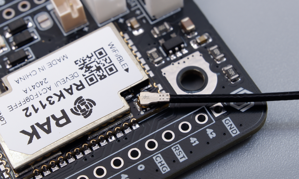
Figure: The 2.4 GHz PCB antenna cable securely snapped onto the micro-coaxial WiFi/BLE MHF4 connector on the RAK3112 module.
If your Cubicore Devboard is in its default factory configuration, the 2.4 GHz PCB antenna is pre-mounted within the baseplate channel and its MHF4 connector is already secured under the Antenna Locker Plate—no manual antenna mating is needed.
If you have removed the board from its baseplate (for example, to solder the expansion headers), refer to the in-case reassembly guide in Getting Started for step-by-step cable routing and antenna locker plate installation instructions.
Never initialize Wi-Fi or Bluetooth radios without attaching the 2.4 GHz PCB antenna to the ANT_WIFI port. Transmitting without an antenna creates impedance mismatch that reflects high RF power back into the silicon power amplifiers, causing excessive heating and potential permanent damage.
The ESP32-S3 microcontroller supports standard 802.11 b/g/n Wi-Fi on the 2.4 GHz band and Bluetooth 5.0 (BLE). It does not support 5.0 GHz or 6.0 GHz Wi-Fi networks. Ensure your Wi-Fi router broadcasts a 2.4 GHz network.
2. Part 1 (Wi-Fi): Network Health Diagnostic & Signal Strength (RSSI)
In real-world IoT deployments, a device must verify local network health before sending mission-critical telemetry. This diagnostic sketch performs an active 2.4 GHz site survey, reports signal strength in decibel-milliwatts (dBm), and connects to your local access point with real-time LED status feedback.
Understanding Wi-Fi Signal Strength (RSSI):
-30 to -60 dBm: Excellent signal (ideal for rapid firmware downloads and high-throughput streaming).-60 to -75 dBm: Good signal (reliable for standard IoT telemetry and NTP clock sync).-75 to -85 dBm: Weak signal (frequent packet drops, higher retries, increased battery drain).<-85 dBm: Unusable (high packet loss, connection dropouts).
Wi-Fi Diagnostic & Site Survey Sketch
/*
 * Cubicore Devboard - Wi-Fi Network Diagnostic & Site Survey
 * Scans 2.4 GHz networks, connects to AP, and provides LED status feedback
 */

#include <WiFi.h>

// --- REPLACE WITH YOUR NETWORK CREDENTIALS ---
const char* WIFI_SSID     = "YOUR_WIFI_SSID";
const char* WIFI_PASSWORD = "YOUR_WIFI_PASSWORD";

// Onboard Status LEDs
#define PIN_LED_BLUE   45  // Blinks during connection, solid when connected
#define PIN_LED_GREEN  46  // Blinks on successful ping/diagnostic

void performSiteSurvey() {
  Serial.println("\n[SITE SURVEY] Scanning 2.4 GHz Wi-Fi networks...");
  int networkCount = WiFi.scanNetworks();

  if (networkCount == 0) {
    Serial.println("[SITE SURVEY] No networks found. Check 2.4 GHz antenna connection.");
  } else {
    Serial.printf("[SITE SURVEY] Found %d networks:\n", networkCount);
    Serial.println("---------------------------------------------------------------");
    Serial.printf("%-25s | %-6s | %-8s | %s\n", "SSID", "CH", "RSSI", "Quality Rating");
    Serial.println("---------------------------------------------------------------");

    for (int i = 0; i < networkCount; ++i) {
      int32_t rssi = WiFi.RSSI(i);
      String rating;
      if (rssi >= -60)      rating = "Excellent";
      else if (rssi >= -75) rating = "Good";
      else if (rssi >= -85) rating = "Fair (Weak)";
      else                  rating = "Poor (Unusable)";

      Serial.printf("%-25.25s | %-6d | %-4d dBm | %s\n",
                    WiFi.SSID(i).c_str(), WiFi.channel(i), rssi, rating.c_str());
    }
    Serial.println("---------------------------------------------------------------\n");
  }
}

void connectToWiFi() {
  Serial.printf("[WIFI] Connecting to '%s'...", WIFI_SSID);
  WiFi.mode(WIFI_STA);
  WiFi.begin(WIFI_SSID, WIFI_PASSWORD);

  unsigned long startAttempt = millis();
  bool ledState = false;

  // Blink Blue LED while connecting (timeout after 20 seconds)
  while (WiFi.status() != WL_CONNECTED && (millis() - startAttempt < 20000)) {
    ledState = !ledState;
    digitalWrite(PIN_LED_BLUE, ledState ? HIGH : LOW);
    delay(250);
    Serial.print(".");
  }

  if (WiFi.status() == WL_CONNECTED) {
    digitalWrite(PIN_LED_BLUE, HIGH); // Solid Blue LED indicates active connection
    Serial.println("\n[WIFI] Connected successfully!");
    Serial.printf("[WIFI] IP Address:  %s\n", WiFi.localIP().toString().c_str());
    Serial.printf("[WIFI] Gateway IP:  %s\n", WiFi.gatewayIP().toString().c_str());
    Serial.printf("[WIFI] Subnet Mask: %s\n", WiFi.subnetMask().toString().c_str());
    Serial.printf("[WIFI] Signal RSSI: %d dBm\n", WiFi.RSSI());
    Serial.printf("[WIFI] MAC Address: %s\n", WiFi.macAddress().c_str());
  } else {
    digitalWrite(PIN_LED_BLUE, LOW);
    Serial.println("\n[WIFI] Connection failed. Verify SSID, password, and 2.4 GHz router band.");
  }
}

void setup() {
  Serial.begin(115200);
  while (!Serial && millis() < 3000);

  pinMode(PIN_LED_BLUE, OUTPUT);
  pinMode(PIN_LED_GREEN, OUTPUT);
  digitalWrite(PIN_LED_BLUE, LOW);
  digitalWrite(PIN_LED_GREEN, LOW);

  Serial.println("\n==========================================");
  Serial.println("   Cubicore Devboard - Wi-Fi Diagnostics  ");
  Serial.println("==========================================");

  // 1. Scan nearby environmental networks
  performSiteSurvey();

  // 2. Connect to the designated access point
  connectToWiFi();
}

void loop() {
  // Heartbeat loop - keep status confirmed
  if (WiFi.status() == WL_CONNECTED) {
    digitalWrite(PIN_LED_GREEN, HIGH);
    delay(100);
    digitalWrite(PIN_LED_GREEN, LOW);
  }
  delay(4900);
}

Figure: Arduino Serial Monitor displaying the detected 2.4 GHz access points, channels, and RSSI signal quality ratings.
3. Real-World Internet Verification: NTP Real-Time Clock Sync
To verify that the Devboard has active, two-way internet routing beyond the local subnet, synchronize the ESP32-S3 internal hardware RTC with global Network Time Protocol (NTP) servers (pool.ntp.org).
Accurate UTC timestamps are critical for IoT sensor logs and LoRaWAN payload sequencing. This standalone sketch connects to Wi-Fi, fetches authoritative epoch time from the internet, and continuously maintains and prints real-world clock time:
/*
 * Cubicore Devboard - Real-Time Clock (RTC) NTP Synchronization
 * Connects to 2.4 GHz Wi-Fi, fetches UTC time from pool.ntp.org,
 * and maintains continuous authoritative epoch time in loop().
 */

#include <WiFi.h>
#include "time.h"

// --- REPLACE WITH YOUR NETWORK CREDENTIALS ---
const char* WIFI_SSID     = "YOUR_WIFI_SSID";
const char* WIFI_PASSWORD = "YOUR_WIFI_PASSWORD";

// NTP Server Configuration
const char* NTP_SERVER          = "pool.ntp.org";
const long  GMT_OFFSET_SEC      = 0;     // 0 for UTC (e.g. 28800 for UTC+8)
const int   DAYLIGHT_OFFSET_SEC = 0;     // Daylight savings offset in seconds

// Onboard Status LEDs
#define PIN_LED_BLUE   45  // Blinks during Wi-Fi connect, solid when synced
#define PIN_LED_GREEN  46  // Heartbeat pulse

void printLocalTime() {
  struct tm timeinfo;
  if (!getLocalTime(&timeinfo)) {
    Serial.println("[NTP ERROR] Failed to obtain time from RTC.");
    return;
  }
  char timeString[64];
  strftime(timeString, sizeof(timeString), "%Y-%m-%d %H:%M:%S UTC", &timeinfo);
  Serial.printf("[RTC CLOCK] Current Time: %s\n", timeString);
}

void setup() {
  Serial.begin(115200);
  while (!Serial && millis() < 3000);

  pinMode(PIN_LED_BLUE, OUTPUT);
  pinMode(PIN_LED_GREEN, OUTPUT);
  digitalWrite(PIN_LED_BLUE, LOW);
  digitalWrite(PIN_LED_GREEN, LOW);

  Serial.println("\n==========================================");
  Serial.println("   Cubicore Devboard - NTP Time Client    ");
  Serial.println("==========================================");

  // 1. Connect to Wi-Fi
  Serial.printf("[WIFI] Connecting to '%s'...", WIFI_SSID);
  WiFi.mode(WIFI_STA);
  WiFi.begin(WIFI_SSID, WIFI_PASSWORD);

  unsigned long start = millis();
  bool ledState = false;
  while (WiFi.status() != WL_CONNECTED && (millis() - start < 20000)) {
    ledState = !ledState;
    digitalWrite(PIN_LED_BLUE, ledState ? HIGH : LOW);
    delay(250);
    Serial.print(".");
  }

  if (WiFi.status() != WL_CONNECTED) {
    digitalWrite(PIN_LED_BLUE, LOW);
    Serial.println("\n[WIFI ERROR] Connection failed. Check credentials.");
    return;
  }

  digitalWrite(PIN_LED_BLUE, HIGH);
  Serial.println("\n[WIFI] Connected! IP: " + WiFi.localIP().toString());

  // 2. Configure time via NTP server
  Serial.println("[NTP] Fetching network time from " + String(NTP_SERVER) + "...");
  configTime(GMT_OFFSET_SEC, DAYLIGHT_OFFSET_SEC, NTP_SERVER);

  // 3. Confirm RTC synchronization
  printLocalTime();
  Serial.println("[SUCCESS] Internal RTC synchronized successfully.\n");
}

void loop() {
  // Print updated clock every 5 seconds
  printLocalTime();

  // Heartbeat pulse on Green LED
  digitalWrite(PIN_LED_GREEN, HIGH);
  delay(100);
  digitalWrite(PIN_LED_GREEN, LOW);

  delay(4900);
}
4. Part 2 (BLE): Wireless Serial Terminal over Bluetooth (BLE UART)
When your Cubicore Devboard is disconnected from your computer and operating on battery or inside an enclosure, you need a way to monitor debug logs and send commands without tethering a physical cable.
The Nordic UART Service (NUS) protocol is the industry standard for wireless serial communication over Bluetooth Low Energy.
Standard BLE UART UUIDs:
- Base Service UUID:
6E400001-B5A3-F393-E0A9-E50E24DCCA9E - RX Characteristic (Write to Devboard):
6E400002-B5A3-F393-E0A9-E50E24DCCA9E - TX Characteristic (Stream from Devboard):
6E400003-B5A3-F393-E0A9-E50E24DCCA9E
Complete BLE UART Wireless Console Sketch
/*
 * Cubicore Devboard - BLE UART Wireless Serial Console
 * Streams live telemetry to mobile apps and accepts remote commands
 */

#include <BLEDevice.h>
#include <BLEServer.h>
#include <BLEUtils.h>
#include <BLE2902.h>

#define PIN_LED_BLUE   45  // Connection indicator LED
#define PIN_LED_GREEN  46  // Remotely controlled command LED
#define PIN_VBAT_SENSE 1   // Battery voltage sense on Devboard GPIO 1

#define SERVICE_UUID           "6E400001-B5A3-F393-E0A9-E50E24DCCA9E"
#define CHARACTERISTIC_UUID_RX "6E400002-B5A3-F393-E0A9-E50E24DCCA9E"
#define CHARACTERISTIC_UUID_TX "6E400003-B5A3-F393-E0A9-E50E24DCCA9E"

BLEServer*         pServer        = NULL;
BLECharacteristic* pTxCharacteristic = NULL;
bool               deviceConnected = false;
bool               oldDeviceConnected = false;

// Battery voltage reader (1.0M / 1.5M divider)
float getBatteryVoltage() {
  uint32_t raw_mv = analogReadMilliVolts(PIN_VBAT_SENSE);
  return (raw_mv * 1.6667f) / 1000.0f;
}

// Server Connection Callbacks
class MyServerCallbacks: public BLEServerCallbacks {
    void onConnect(BLEServer* pServer) {
      deviceConnected = true;
      digitalWrite(PIN_LED_BLUE, HIGH); // Solid Blue LED when phone is connected
    };

    void onDisconnect(BLEServer* pServer) {
      deviceConnected = false;
      digitalWrite(PIN_LED_BLUE, LOW);
    }
};

// Characteristic Receive Callbacks (Commands from Phone)
class MyCallbacks: public BLECharacteristicCallbacks {
    void onWrite(BLECharacteristic *pCharacteristic) {
      String rxValue = pCharacteristic->getValue();

      if (rxValue.length() > 0) {
        char cmd = rxValue[0];
        Serial.printf("[BLE RX] Command received: '%c'\n", cmd);

        switch (cmd) {
          case '1':
            digitalWrite(PIN_LED_GREEN, HIGH);
            pTxCharacteristic->setValue("ACK: Green LED ON\n");
            pTxCharacteristic->notify();
            break;

          case '0':
            digitalWrite(PIN_LED_GREEN, LOW);
            pTxCharacteristic->setValue("ACK: Green LED OFF\n");
            pTxCharacteristic->notify();
            break;

          case 'b':
          case 'B': {
            char batMsg[64];
            snprintf(batMsg, sizeof(batMsg), "BATT: %.2f V\n", getBatteryVoltage());
            pTxCharacteristic->setValue(batMsg);
            pTxCharacteristic->notify();
            break;
          }

          default:
            pTxCharacteristic->setValue("ERR: Unknown command ('1'=ON, '0'=OFF, 'b'=VBat)\n");
            pTxCharacteristic->notify();
            break;
        }
      }
    }
};

void setup() {
  Serial.begin(115200);
  while (!Serial && millis() < 3000);

  pinMode(PIN_LED_BLUE, OUTPUT);
  pinMode(PIN_LED_GREEN, OUTPUT);
  digitalWrite(PIN_LED_BLUE, LOW);
  digitalWrite(PIN_LED_GREEN, LOW);

  analogReadResolution(12);
  analogSetAttenuation(ADC_11db);

  Serial.println("\n[INIT] Initializing Cubicore BLE Wireless Console...");

  // Initialize BLE Device
  BLEDevice::init("Cubicore-Devboard");
  pServer = BLEDevice::createServer();
  pServer->setCallbacks(new MyServerCallbacks());

  // Create Nordic UART Service
  BLEService *pService = pServer->createService(SERVICE_UUID);

  // TX Characteristic (Notify to Phone)
  pTxCharacteristic = pService->createCharacteristic(
                        CHARACTERISTIC_UUID_TX,
                        BLECharacteristic::PROPERTY_NOTIFY
                      );
  pTxCharacteristic->addDescriptor(new BLE2902());

  // RX Characteristic (Write from Phone)
  BLECharacteristic *pRxCharacteristic = pService->createCharacteristic(
                                           CHARACTERISTIC_UUID_RX,
                                           BLECharacteristic::PROPERTY_WRITE
                                         );
  pRxCharacteristic->setCallbacks(new MyCallbacks());

  // Start Service & Advertising
  pService->start();
  BLEAdvertising *pAdvertising = BLEDevice::getAdvertising();
  pAdvertising->addServiceUUID(SERVICE_UUID);
  pAdvertising->setScanResponse(true);
  pAdvertising->setMinPreferred(0x06); // iPhone connection optimization
  pAdvertising->setMinPreferred(0x12);
  BLEDevice::startAdvertising();

  Serial.println("[BLE] Advertising as 'Cubicore-Devboard'. Ready to connect.");
}

void loop() {
  static unsigned long lastStreamTime = 0;

  // Stream live telemetry every 2 seconds when phone is connected
  if (deviceConnected && (millis() - lastStreamTime > 2000)) {
    lastStreamTime = millis();

    char telemetry[128];
    snprintf(telemetry, sizeof(telemetry),
             "[TELEMETRY] Uptime: %lu s | VBat: %.2f V | Heap: %lu B\n",
             millis() / 1000, getBatteryVoltage(), esp_get_free_heap_size());

    pTxCharacteristic->setValue(telemetry);
    pTxCharacteristic->notify();
    Serial.print("[BLE TX] ");
    Serial.print(telemetry);
  }

  // Handle re-advertising on disconnect
  if (!deviceConnected && oldDeviceConnected) {
    delay(500); // Give Bluetooth stack time to settle
    pServer->startAdvertising();
    Serial.println("[BLE] Device disconnected. Restarting advertising...");
    oldDeviceConnected = deviceConnected;
  }
  if (deviceConnected && !oldDeviceConnected) {
    oldDeviceConnected = deviceConnected;
  }
}

Figure: Arduino Serial Monitor confirming BLE stack initialization and active advertising as 'Cubicore-Devboard'.
5. Testing with a Mobile Phone App
You can connect to your Devboard from any smartphone without writing a mobile app:
Recommended Free Mobile Apps:
- Android: Serial Bluetooth Terminal (by Kai Morich) or nRF Connect (by Nordic Semiconductor).
- iOS: nRF Connect for Mobile or LightBlue.
Quick Connection Steps:
- Install and launch Serial Bluetooth Terminal or nRF Connect.
- Enable Bluetooth on your smartphone and search for devices.
- Locate and tap
Cubicore-Devboard. - Once connected:
- The onboard Blue LED (
Devboard GPIO 45) illuminates solid. - Live telemetry lines start streaming across your screen every 2 seconds.
- The onboard Blue LED (
- In the input box, type
'1'and tap Send → The Green LED (Devboard GPIO 46) turns ON. - Type
'0'and tap Send → The Green LED turns OFF. - Type
'b'and tap Send → The board responds with its current battery voltage.
6. Radio Power Discipline for Battery Deployments
While Wi-Fi and Bluetooth provide high-bandwidth connectivity, their power consumption is significant compared to Sub-GHz LoRa:
| Radio Mode | Active Current Consumption | Typical Use Case |
|---|---|---|
| Wi-Fi Active (TX/RX) | ~80 mA to 120 mA | Fast NTP sync, burst cloud uploads, firmware OTA |
| BLE Advertising / Connected | ~25 mA to 45 mA | In-field diagnostics, wireless configuration |
| SX1262 LoRa Active TX (+22 dBm) | ~118 mA | Long-range telemetry bursts (10–50 ms airtime) |
| SX1262 LoRa Sleep + ESP32 Deep Sleep | ~15 µA to 25 µA | Long-term battery/solar field standby |
Shutting Down 2.4 GHz Radios to Save Power
When your Wi-Fi or BLE task completes, explicitly power down the radios to preserve battery capacity:
// 1. Turn OFF Wi-Fi completely
WiFi.disconnect(true);
WiFi.mode(WIFI_OFF);

// 2. Turn OFF Bluetooth Low Energy controller
BLEDevice::deinit(true);

// System current immediately drops, preparing the board for deep sleep or LoRa-only operation.
7. Troubleshooting Wi-Fi & BLE Issues
| Symptom | Probable Cause | Recommended Fix |
|---|---|---|
| Wi-Fi Site Survey finds 0 networks | Missing 2.4 GHz antenna or loose MHF4 connector | Inspect the micro-coaxial snap connector on ANT_WIFI. Re-seat firmly until an audible click is heard. |
Connection times out with WL_CONNECT_FAILED | Router is broadcasting on 5 GHz only or 802.11ax mode | Verify that your Wi-Fi access point has 2.4 GHz enabled with WPA2/WPA3 mixed personal security. |
Smartphone cannot discover Cubicore-Devboard | Bluetooth permissions missing on phone or device still bonded | Grant "Nearby Devices" / Bluetooth permissions to your mobile app. Reset the board via the RST pushbutton. |
| BLE connection drops immediately after pairing | Inadequate USB power during simultaneous radio usage | Ensure your workstation USB-C port provides at least 500 mA. Avoid unpowered USB keyboard hubs. |
Next Steps
Now that you have mastered 2.4 GHz Wi-Fi diagnostics and wireless BLE serial communication on the Cubicore Devboard, proceed to Sub-GHz long-range networking:
- Joining a LoRaWAN Network — Transmit long-range sensor telemetry over AS923-3, US915, or EU868 to the Cubicore Gateway.
- LoRa P2P — Direct Devboard-to-Devboard RF packet transmission without network servers.